Stay up-to-date with changes to the Website
New Website Content
Checkout "New Content on the Website" about possible future online training.
Success is where preparation and opportunity meet.
Website Disclaimer
This site provides educational material. It is not designed to promote any company or diagnostic equipment. No compensation has been accepted for displaying equipment-specific information on this website. All pictures, captures, snapshots, and other images are designed solely to educate and inform the viewer.
The author has made every reasonable effort to ensure the material is accurate and current.
No part of this website may be reproduced, stored in a central system, transmitted, or duplicated in any form or by any means, electronic, mechanical, photocopying, recording, or otherwise, without the copyright holder's written permission.
Updated 02/16/2026
Copyright© 2023 RLEscalambre. All rights reserved.
About Rick

He taught full-time at Skyline College in San Bruno, CA, for 31 years. As of June 2015, he retired from full-time teaching but continues teaching part-time, conducting industry Webinars and contract training. In addition to teaching Engine performance-related subjects, he coordinated one of California's largest and finest automotive programs.
The college’s facility, equipment, dynamometers, and vehicles allowed him to conduct in-depth research on Engine performance, Computer Controls, On-Board Diagnostic Two (OBDII) System Operation & Diagnosis, and Evaporative Emission Systems.
Rick is a respected author and editor of Engine Performance, Evaporative Emission Systems, and Computer Controls books. He aims to provide information to help teachers and technicians perform their jobs more effectively.
***New Website Content***
If you have previously visited this website, this page allows you to see what information has been recently added or updated. This way, you do not have to search the entire site. The plan is to constantly add and update the website.
| Date | Section | Topic |
| 01/20/2025 | MODE $03 Emission Related Diagnostic Information | Setting a Diagnostic Trouble Code |
| 4/01/2025 | Articles by Rick | Enhanced Fuel Trim |
| 4/01/2025 | Articles by Rick | The Story of the Stolen Catalytic Converter |
| 4/01/2025 | Articles by Rick | What it means to be an Educator |
| 04/01/2025 | Articles by Rick | Disjointed |
| 11/09/2025 | Training Opportunities | ASE Education Alliance Conference 2026 |
| 11/09/2025 | Training Opportunities | ASE Free Webinars |
| 11/12/2025 | Unified Diagnostic Services | Current List of Certified Vehicles |
| 12/08/2025 | PID $41 with HP Tuner | 2018 Nissan O2 Readiness Status using PID $41 |
| PID $41 with HP Tuner | 2018 Nissan Catalytic Readiness Status using PID $41 | |
| 12/15/2025 | Readiness Status Update | Readiness Status $01/$01 Update |
| 12/18/2025 | Readiness Flag Update PID $41 | Readiness Status $01/$41 Update |
| 12/20/2025 | Future Online Training | Information about possible online training in the future. |
| 01/21/2026 | Unified Diagnostic Services | Vehicles Currently Certified for OBDonUDS |
| 02/16/2026 | Toyota Slight Misfire | |
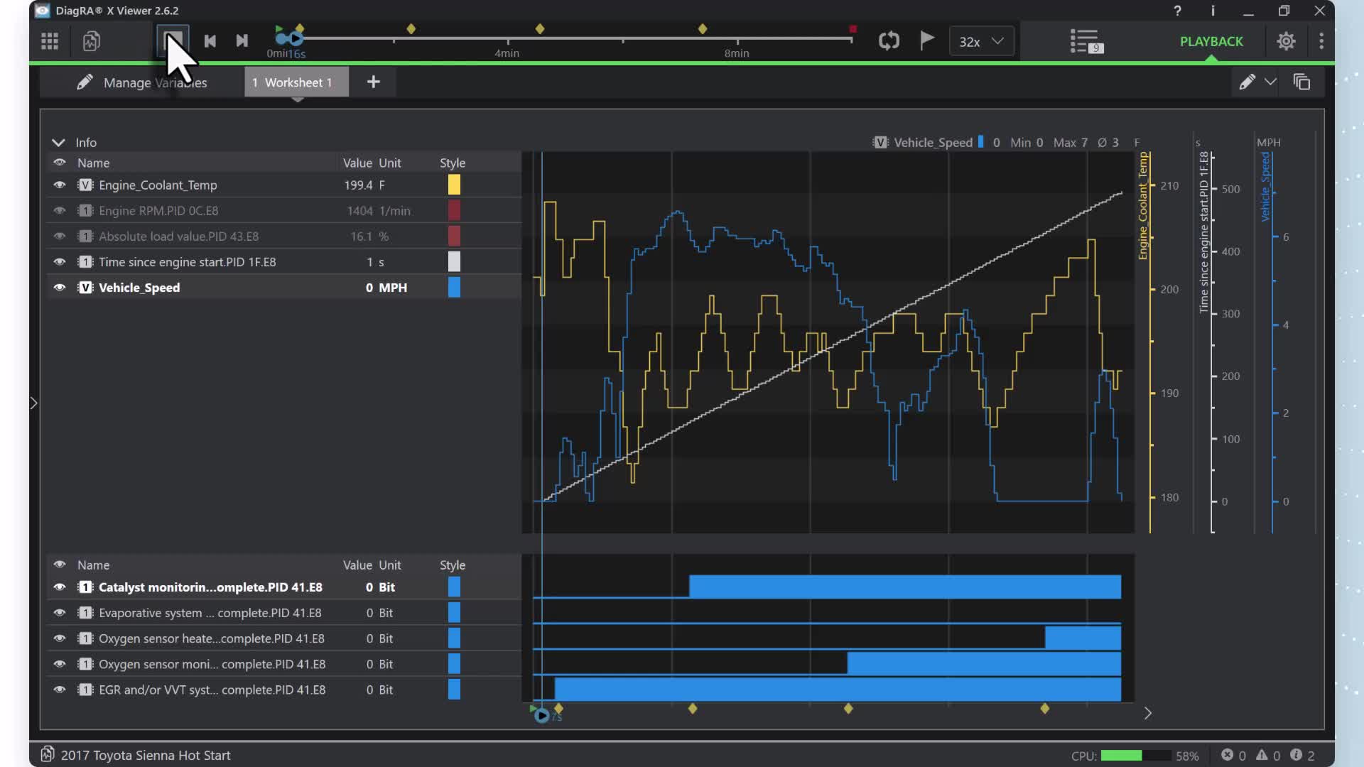
| 2/16/2026 | Toyota V6 Drive Cycle | Drive Cycle Pattern - Cold Start |
| 02/16/2026 | Toyota V6 Drive Cycle | Drive Cycle Pattern - Hot Restart |
Computer Controls Introduction
Introduction to Automotive Computer Controls
For years, automotive engineers found it challenging to design mechanical, vacuum, and hydraulic systems that consistently and accurately deliver the needed results. Systems strayed widely from the ideal air/fuel ratios because they could not monitor combustion or accurately control fuel delivery. They required elaborate emissions control systems to meet stringent exhaust emissions standards. These systems required much maintenance and sometimes were complicated, making them difficult to repair. If automotive engineers concentrated on increasing fuel economy and lowering emissions, performance and driveability would suffer. If they focused on reducing emissions, the economy, driveability, and performance would suffer. Electronic engine controls allow automotive engineers to restore good driveability, increase economy, lower exhaust emissions, and increase performance.
Good driveability is what the driver expects from a properly functioning engine, including easy starting, smooth idle, good acceleration through all speeds, instant response, and full power. Driveability concerns arise when a vehicle stalls, hesitates or stumbles, idles rough, surges, lacks power, is hard to start, or fails to start.
The official start of On-Board Diagnostics I (OBD I) was in 1988 (1). At that time, the California Air Resources Board (CARB) required that all vehicles sold new in California be equipped with a Check Engine Light (CEL). CARB required manufacturers to monitor the items in the area (2) below.
On-Board Diagnostics II (OBD II) was officially required to be equipped on all 1996 and newer passenger cars and light-duty trucks. Some manufacturers installed OBD II on 1994 and 1995 model-year vehicles. CARB required manufacturers to monitor the below.
The basic principles of Computer Fundamentals do not change. The foundation is always Input, Process, and Output. An important note is to look at where the scan tool is placed in the system. It takes processed data from the ECM/PCM and decodes it so the technician can read it. Remember that connecting a scan tool means adding another module to the network.

Computer Fundamentals
All computers rely on the principles of power and ground: generally, there are at least two battery feeds and two grounds. Computer operation is most reliable when the system voltage is 12-15 volts. The computer may enter a fail-safe mode if the operating voltage drops below ten or exceeds 17 volts.

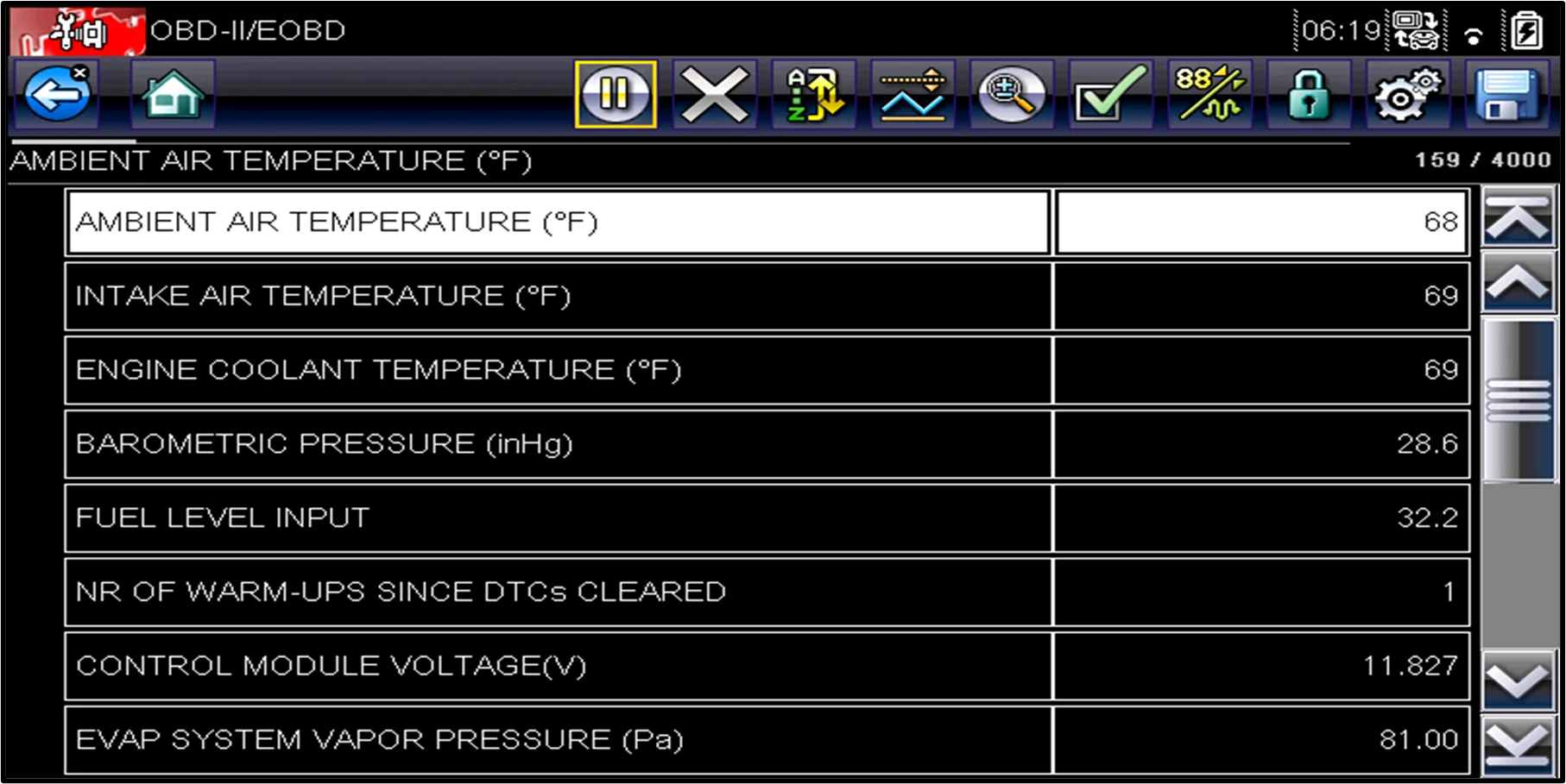
The ECM/PCM will have a Keep Alive Memory (KAM) that should always be B+. With the ignition in the Start or Run position, at least one, possibly two terminals, should have battery/charging voltage for proper ECM/PCM operation. The following pictures demonstrate these voltages. Note that the 11.82-volt key-on engine-off is lower than normal, so don't overlook a potential battery problem.
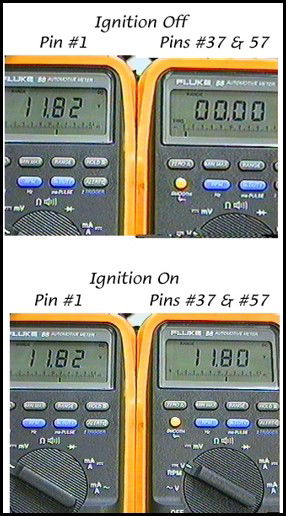
The quality of the connections at the battery and any ground point should always be considered. The ECM/PCM grounds can be located in various locations. They can be affected by corrosion, loose connections, and broken wire strands, which can lead to an increased voltage drop at these points.

Before 1990, a typical ground-to-ground voltage drop could be as high as .100v or 100mV. Since then, a typical ground-to-ground voltage drop is .050v or 50mV. If a higher-than-normal voltage drops at a ground connection, the ECM/PCM will see a higher-than-normal voltage reading from the affected circuit.

MORE CONTENT TO BE ADDED; PLEASE CHECK BACK!

Types of Scan Tools
An automotive scan tool is an electronic device used by technicians to decode serial data, communicate with modules, diagnose problems, and, in some cases, reprogram vehicle control modules.
Remember that a scan tool is only as good as the user’s understanding of the data. When used with the proper reference materials, a scan tool can significantly help a knowledgeable, experienced technician perform computer-related diagnostics. Often, the device is more than a help; it's a necessity. But it cannot solve problems on its own. Understanding the data and accurately interpreting the displayed information is key. The technician, not the tool, is the diagnostician.
Five Types of Scan Tools are available:
- Code Readers – They are inexpensive and quick, but they might not provide all the Global MODEs.
- Bluetooth for Smartphones – moderately priced but might not provide all the Global MODEs.
- Aftermarket will display Global OBD II and Enhanced (OEM Level in most cases).
- OEM factory-specific, but they may not include any or all of the Global OBD II MODES.
- Aftermarket Tuner Dongle.
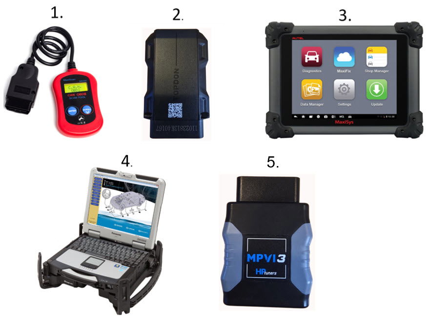
A scan tool can be wired or Wireless (Bluetooth), handheld, or PC-based. To achieve a higher level of diagnostics, a Global Code Reader and Bluetooth for iOS and Smartphones will not suffice.
Two options are available when using an aftermarket scan tool and technician, and there are advantages to both:
Global (EOBD) OBD II:
- The system might not be identified by Make, Model, or Year (Note: Some Global Scan Tools can identify the vehicle based on the VIN).
- Talks in standard Protocols to all systems.
- Pre-CAN PIDS can be limited.
- PIDS can be extensive, and some PIDS the Aftermarket Enhanced scan tools do not provide.
- Provide many PIDS similar to Enhanced OBD II, but may identify them using different terminology.
- It provides no bi-directional testing and can only command the EVAP Vent Solenoid On, if available.
- It will communicate with emission-related modules like the Engine Control Module (ECM) and Transmission Control Module (TCM).
Aftermarket Enhanced (OEM) OBD II:
- Does identify the system by VIN, Make, Model, and Year.
- Talks using the protocol specific to the individual manufacturer.
- It provides many PIDS similar to Global but may identify them using different terminology.
- It might provide PIDS not found in Global OBD II. PIDS might be divided into pages.
- Provides Bi-Directional Testing of specific Outputs.
- It may provide reprogramming options.
- Can communicate with most, if not all, modules on the vehicle.
Additional Scan Tool Features:
Combining an aftermarket Scan tool and online Service Information
The global scan tool can be combined with an online service information subscription. In the following video, the INNOVA 7111 tablet will be combined with MOTOR Repair Service. Once a confirmed DTC triggers a MIL, the tool will link to MOTOR. There is a fee for accessing this online service. This video shows a first signup to MOTOR with a 30-day free trial.
MORE INFORMATION TO BE ADDED SOON.
Pre and Post Scans
The importance of pre- and post-scan data cannot be overstated. With the addition of numerous onboard computers/modules, it is essential to understand what they contain and how they could impact the diagnostic process. It helps the technician to avoid the "I didn't know" syndrome. The post-scan verifies repair for the technician and the consumer.
Under current regulations, per SAE 1979-1 Global OBDII, the only computers available for viewing are the engine and transmission. The OEMs are not required to make this information available to the global scan tool.
On the enhanced side of the aftermarket scan tool, many computers/modules can store valuable information. The critical thing to remember is that some of these computers/modules may be storing information that prevents a process, such as running readiness flag monitor tests.
Here are the pre- and post-scan results from an INNOVA 7111 scan tool. This vehicle underwent a pre-scan and had nothing to hide.

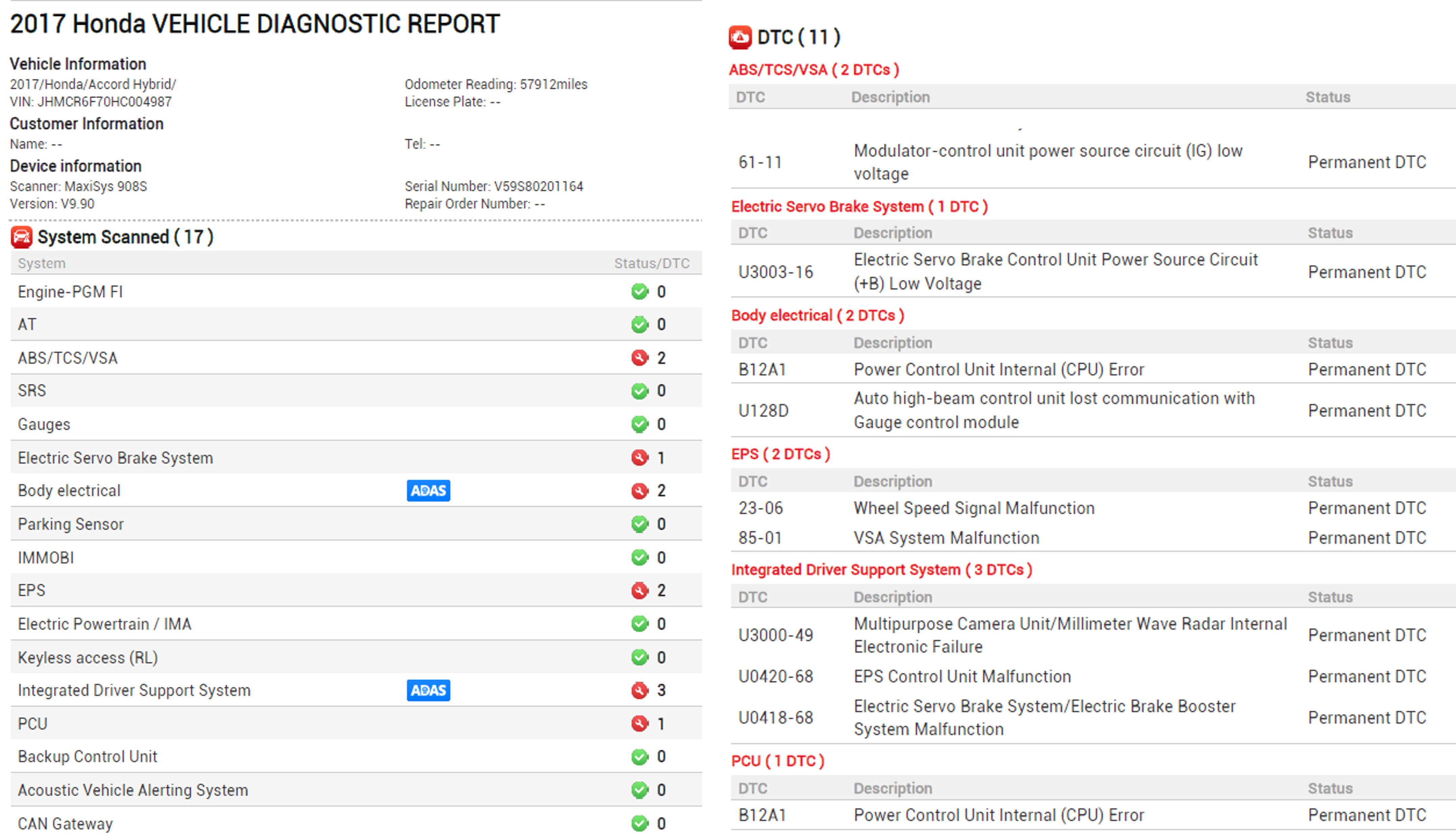
Here is a pre-scan from an AUTEL scan tool. This vehicle had a lot to hide from the global scan tool.
Network Topology Mapping
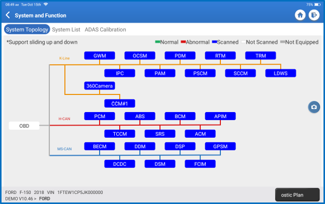
Network Topology Mapping is a graphical layout of the network. It serves a few purposes: it highlights the computers on the network, displays the number of DTCs stored in each computer, and provides quick access to each computer.
Secure Gateway - AUTO AUTHORITY
Click this link, Homepage - AutoAuth, to learn more.
OBD II Global MODES
| MODE $01 | Readiness Flag Status and Parameter Identification (PIDs) |
| MODE $02 | Powertrain Freeze Frame Data (FFD) |
| MODE $03 | Emission Related Diagnostic Trouble Codes (DTC) |
| MODE $04 | Clear/Reset Emission Related Diagnostic Information |
| MODE $05 | Oxygen Sensor Monitoring Test Results |
| MODE $06 | Onboard Monitoring Test Results and Parameters |
| MODE $07 | Two Trip Pending Diagnostic Trouble Code |
| MODE $08 | Request Control of Onboard Component |
| MODE $09 | Request Vehicle Information |
| MODE $0a | Permanent Diagnostic Trouble Code (PDTC) |
Some aftermarket scan tools will display the Hexadecimal symbol ($), others will not.
Snap-On Global Scan Tool

AUTEL Global Scan Tool

$01 Parameter Identification (PIDs)
MODE $01 Parameter Identification (PID) displays emission-related data PIDs such as inputs, outputs, and system status. Pre-CAN global OBD II displayed between 15 and 30 PIDs. For CAN systems, the data list was significantly expanded. When using a global scan tool (GST) to diagnose the vehicle, understand the amount of data available to view and that it will vary depending on the model year and communications protocol.
The following are three examples of PID lists.
1) This data list was captured from a 1997 pre-CAN vehicle. Because of the limited data displayed from some pre-CAN systems, many technicians chose to look at the manufacturer's (OE) specific data. In reality, there was enough information available to diagnose and repair a high percentage of vehicles.

2) This PID list was captured from a 2003 pre-CAN vehicle. For later model pre-CAN systems.

3) This PID list was captured from a 2019 CAN-equipped vehicle. The available PIDs list was expanded because CAN systems transmit data faster and in packets of 6 PIDs per request. In this case, a technician has more help to diagnose more problems through the global side of the scan tool.

Regardless of the year vehicle, learn to customize the PID list to increase the speed at which they update their data. Focus on the need-to-know PIDs, not the nice-to-know PIDs. Think of it this way: you have a one-lane road, and only six cars are moving at the same speed. The next time you drive that road, there are 30 cars on the road moving at the same speed. Which one is faster to travel through?
$01/$01 Readiness Flag Status
MODE $01, PID $01 represents the Readiness Flag Status for Engine Computer (7E8) and Transmission Computer (7E9). Readiness flag status indicates that each flag has completed testing at least once since the memory was last reset. Each Readiness Flag consists of one or more individual monitor tests. Once all required monitor tests are complete, the Readiness Flag Status will display "Complete". This information can be used to verify a repair by running specific monitor test(s) and watching the readiness flag flip to COMPLETE. State emissions inspection programs also use it as one requirement to pass or fail the OBD part of the inspection. For the engine computer (7E8), the Readiness Flags are divided into two groups:
- The first group is called Continuous and includes misfire, fuel system, and comprehensive components. This means that they run their monitor tests continuously on each trip when the enable criteria are met. They will be Supported for all vehicles.

- The second group is called non-Continuous and includes the Catalyst, Heated Catalyst, Evaporative Emissions, Secondary Air, Gasoline Particulate Filter, Air Conditioning, Oxygen Sensor, Oxygen Sensor Heater, and the Exhaust Gas Recirculation (EGR) or Variable Valve Timing (VVT) systems. This means that they run their monitor test(s) once per trip when the enable criteria are met. If the system is failing, the computer may repeat the test several times to determine if the system is actually failing. Disregard the Complete status for the Readiness Flags that are not supported.
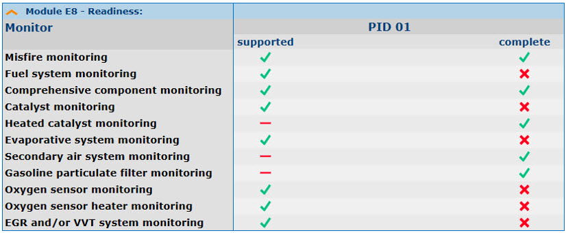
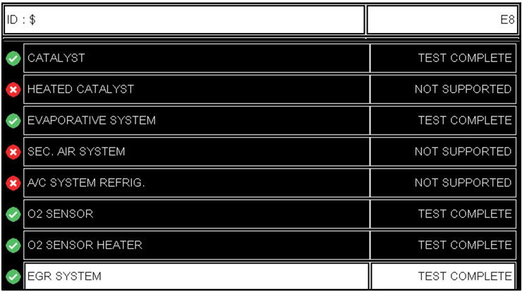
This example shows the "Monitors Complete Since DTC Cleared" status for the engine computer (7E8). Once completed, they can only be reset to Incomplete by performing a MODE $04 diagnostic clear, removing power from the computer, or reprogramming the computer.

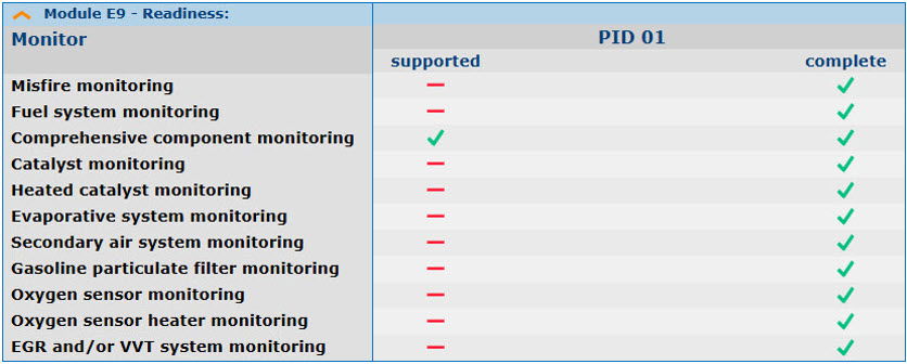
For the transmission computer (7E9), only the Comprehensive Component Readiness Flag is supported. Disregard the Complete status for the Readiness Flags that are not supported.
Check back for more information that will be added soon!
$01/$41 Readiness Flag Status
If you want to verify a repair, turn off a Malfunction Indicator Lamp (MIL) without resetting the memory. Viewing the Readiness Flag Status Complete for Drive Cycle is an option. This is called PID $41 "Monitors Complete this Drive Cycle". At each key-on, all readiness flags will display as Incomplete. Once the monitor tests required to flip the readiness flag to complete run and pass, the status will be updated to COMPLETE for this drive cycle. If any readiness flag remains INCOMPLETE, the monitor test(s) required to flip that flag did not run and/or complete.
Note: this option is only available while connected to a CAN-equipped system. Once readiness flags are COMPLETE for pre-CAN vehicles, the memory must be cleared, setting them back to Incomplete. The vehicle can now be driven to reset the flags to Complete.
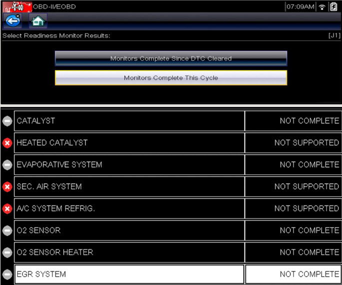
One crucial step that is overlooked because most scan tools do not prompt you is to start the vehicle. Once the vehicle is started, the Readiness Flag Status can now be updated for this drive cycle.
The following prompt is from an INNOVA 7111 tablet.
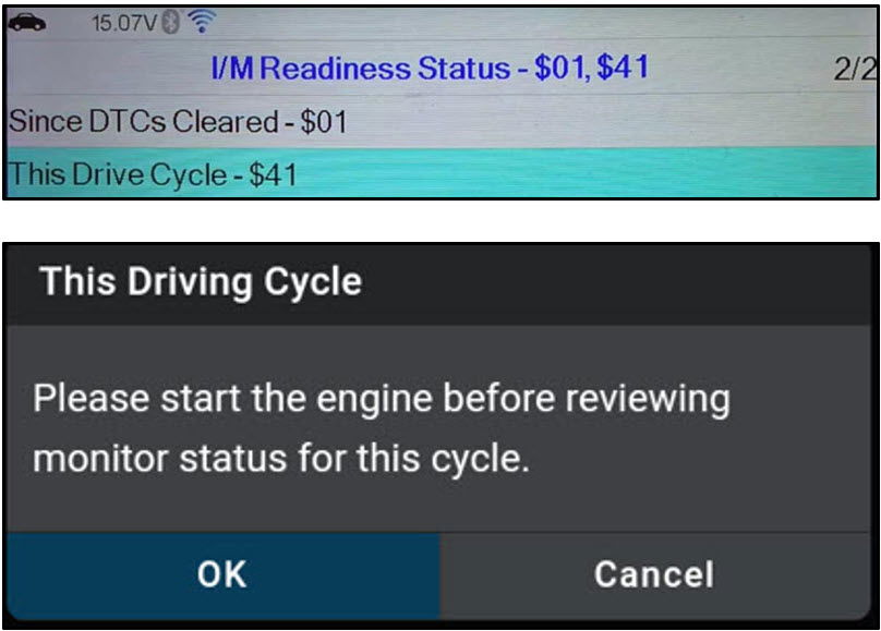
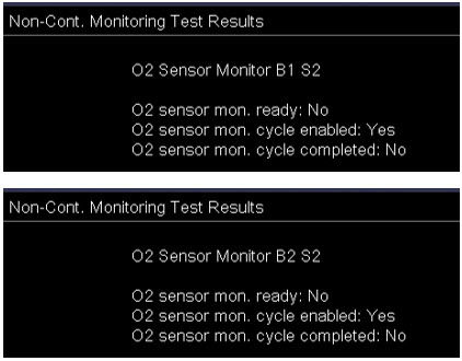
Unfortunately, most scan tool manufacturers do a poor job of reporting the Enable/Disable for this key cycle. Snap-On scan tools support it, but it is located in MODE $06 for the specific monitor test.
The following capture shows the O2 Sensors as Incomplete Since Cleared, Enabled, and not having run this key cycle.
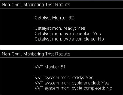
The following capture shows the Catalyst and VVT as Complete Since Cleared, Enabled, and not having run this key cycle.
The following capture shows the Catalyst and EVAP Large Leak as Complete Since Cleared, Disabled, and not having run this key cycle.
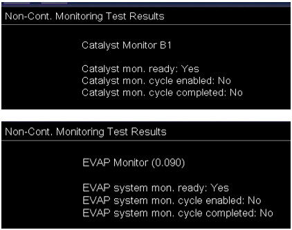
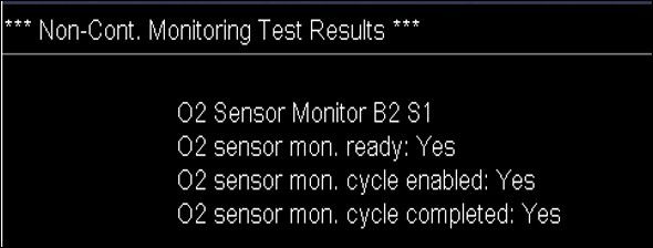
The following capture shows the O2 Sensors as Complete Since Cleared, Enabled, and it has completed this key cycle.
The following capture shows the EVAP Incomplete Since Cleared, Disabled, and has not run this key cycle.
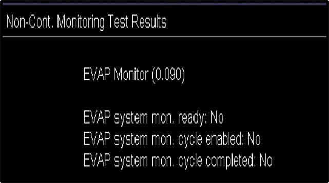
The image above shows "No," "No," and "No." Does this mean the EVAP monitor tests cannot run? There are always exceptions to the rules. If you are working on a Nissan or Infiniti vehicle, the EVAP monitor tests may still run during the current trip. Why? These systems are equipped with a Fuel Temperature Sensor (FTS) inside the fuel tank. These systems do not require a cold soak or startup to run EVAP monitor tests. The computer monitors the FTS for a 4°F increase. Once it increases by 4°F, it indicates a pressure increase in the tank, enabling the EVAP monitor tests to run.
It is also possible to observe the same status when testing EVAP systems that use a vacuum pump to test for a very small leak with the engine off.
Why will a Readiness Flag be Disabled? Typical examples are:
- Engine-off soak not long enough (e.g., cold start temperature conditions not satisfied).
- Monitor test maximum time limit has been exceeded.
- Ambient air temperature too low or too high.
- BARO indicated high altitude (8000ft and above).
- For EVAP, the ambient temperature is not between 40°F and 95°F, and/or the IAT and ECT differential is more than 10°F
- Fuel level is too low. Typically, under 15%.
This screen was captured from an INNOVA SDS43 Tablet. At key-on, EVAP and O2 are Disabled for this trip. For EVAP, it is most likely due to the ambient temperature being out of range, either too cold or too hot. But the Disabled Oxygen Monitor is not specified.
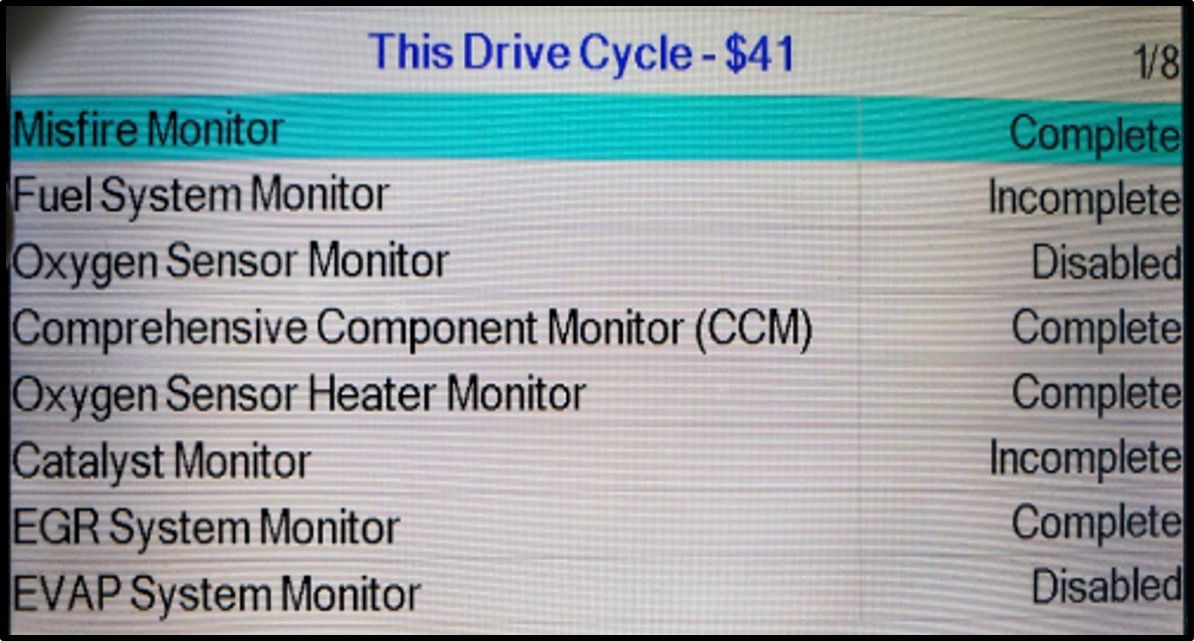
When a Readiness Flag reports Disabled, attempting to complete it during this key cycle may be impossible. Is it possible for a disabled readiness flag status to eventually be completed? The answer is yes, in rare cases. For example, if the vehicle is driven from a low altitude to a high altitude, the readiness flag could flip from enabled to disabled. The readiness flag should not change from disabled to enabled if the conditions change back during the same trip.
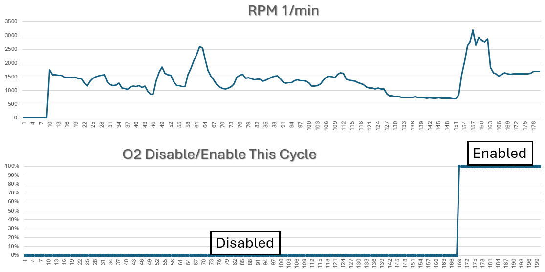
The following capture shows the O2 Readiness Flag Disabled for the current trip. Follow the chart and look at the status switch from disabled to enabled. While this is not the norm, explaining why is difficult. Reviewing the Global OBDII information did not provide a clue to explain why it is disabled. The only explanation is that something in the OEM program is triggering this status.
The following video shows how to check IM Readiness Status. It will show the Readiness Flag Status since the memory was last cleared. It will also show IM Readiness Status for this drive cycle (PID $41).
How to access Monitors Complete this Drive Cycle (PID $41) https://youtu.be/gecNp9Z7ii0
The following videos were recorded using an HP Tuner (www.HPTuner.com). This is an excellent example of what happens when PID $41 is combined with MODE $01 PIDS. The videos show when the O2 and CAT monitor tests are completed and the enabling criteria that led to their completion. After watching the video, look back at the point when the actual monitor tests were completed. The data was collected from a 2018 Nissan Rogue.
2018 Nissan Rogue O2 Readiness Flag Completion https://youtu.be/iOpiIDQCUnk
2018 Nissan Rogue Catalytic Converter Readiness Flag Completion https://youtu.be/gR9vkDf4HXU
Check back for more information that will be added soon!
$02 Powertrain Freeze Frame Data (FFD)
A Freeze Frame of High Priority will overright a stored FFD of lower priority. Newer same-priority DTC/FFD will not overright a previously held FFD of the same priority.
There is only one FFD stored per system. Think of it as having one seat for two or more people (remember musical chairs)?
MORE CONTENT TO BE ADDED, PLEASE CHECK BACK!

$03 Emission Related Diagnostic Trouble Codes (DTC)
A diagnostic trouble code (DTC) indicates that the enable criteria for a monitor test failed outside of a minimum or maximum test limit. If the MIL is illuminated, tailpipe emissions have exceeded 1.5 times the Federal Test Procedure (FTP) standards. MODE $03 reports a DTC once the MIL is commanded ON. This can occur on the first or second consecutive trip. A DTC with the MIL ON is called a confirmed or current DTC. If the MIL is OFF and a DTC is still present, this is referred to as a history DTC. A history DTC remains in memory for 40 warmup cycles if the same code does not reoccur. It can also be cleared using a scan tool or by removing power from the ECM for a while. The length of time depends on the manufacturer.
Defining a Diagnostic Trouble
A five-digit alphanumeric code represents all DTCs. The first letter indicates the function of the monitored component or system that has failed:
P = Powertrain
B = Body
C = Chassis
U = Indicates a network or data link code
The second digit is represented by a number that indicates who is responsible for the code:
0 = Society of Automotive Engineers (SAE)
1 = Manufacturer specific
The third digit indicates the specific system in question. Numbers one through seven indicate a powertrain-related problem. The number eight is reserved for non-powertrain-related problems:
0 = Total system
1 = Air/Fuel metering control
2 = Air/Fuel metering control for injector circuit malfunctions only.
3 = Ignition system or misfire
4 = Emissions Control
5 = Vehicle Speed Control/Idle Control system
6 = ECM and Computer Input/Output Circuits
7 = Transmission
8 = non-Powertrain related
The fourth and fifth digits represent the component, system, or area experiencing the problem. DTC P0306 is described as:
P = Powertrain related
0 = Manufacturer-defined DTC
3 = Ignition system or misfire related problem
06 = Cylinder #6 misfire detected. This MODE retrieves all stored emission-related DTCs from the PCM.
Types of Diagnostic Trouble Codes (DTC)
The ECM can set two kinds of DTC.
1. Functionality DTCs are related to electrical problems set by an open and short circuit. The image below demonstrates a functionality DTC.

2. Rationality/Normality/Plausibility DTCs are performance-related problems. They are set by comparing similar inputs/outputs to see if they make sense. The customer's concern is loss of power under load. The image below shows three related PIDS: TPS, MAP, and RPM. In this case, the ECM must determine which of the three does not make sense. Can you identify the outlier PID that the ECM might flag as incorrect?

Live by codes, die by codes. Sometimes, the ECM can be fooled because the reporting component is malfunctioning. The BARO and FTP PIDs must be checked KOEO and KOER to start an EVAP diagnosis. A DTC for an out-of-range sensor will not be set if the BARO or FTP reports in the yellow zone. This can lead to a false DTC, like a Large Leak because the FTP is not reporting the correct EVAP system pressure. If the BARO reports in this range, it could cause a driveability concern or the suspension of non-continuous readiness monitor tests.

Setting a Pending (2 Trip) or confirmed (1 or 2 Trips) Diagnostic Trouble Code
Setting a pending (2 Trips) or confirmed (1 or 2 Trips) Diagnostic Trouble Code requires numerous steps. Think of it as a sequence of events. If the steps in the sequence occur, a pending or confirmed DTC will be set into memory. A DTC is not easily set because the ECM/PCM needs to be sure the problem actually exists. The first step in the sequence requires specific enable criteria to be met. This will vary for each DTC and between different manufacturers.
(1) Enable Criteria: For the ECM/PCM to monitor a system, specific operating conditions must be met. If the enable criteria are not met, nothing will happen, and a DTC cannot be set for the circuit being monitored. If the enable criteria are met, then ECM/PCM moves on to the next step.
(2) Fault Code Parameters: As long as the enable criteria are met, the ECM/PCM will check the circuit value against internal software. The circuit is checked for voltages that are too low or too high. Additionally, the input is checked against other related inputs to see if the value makes sense. Review the Rationality/Normality/Plausibility section above.
(3) Fault Cycle Counter: The ECM/PCM monitors the circuit to see if the problem is continuous for a minimum amount of time. If it does not last a minimum amount of time, the system passes, the problem is intermittent, and the technician must refer to other resources, from a visual inspection to online assistance. If the problem is continuous and exceeds the minimum time, the circuit fails, and either a pending is set, and it will have to fail on two consecutive trips; or a confirmed DTC is set.
(4) If the issue lasts long enough, either a two-trip Pending DTC or a confirmed DTC and Freeze Frame are set.
If the issue does not last long enough, it is back to basics and the process starts all over again.
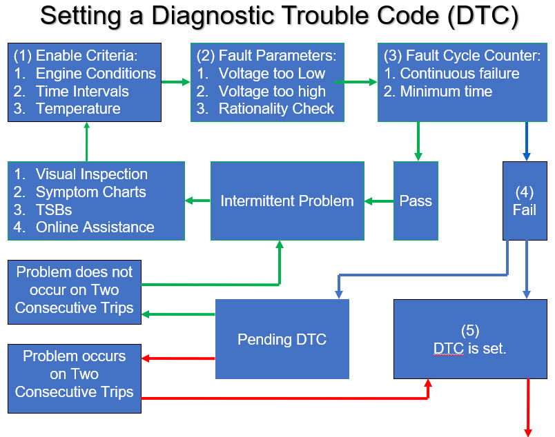
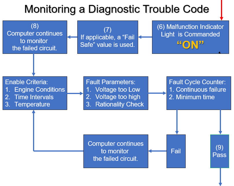
(6) At this point, the MIL is Commanded On.
(7) The ECM/PCM will use a default value to keep the vehicle running and the customer's vehicle off the tow truck. Note: The global side of the scan tool cannot display a default value, it must display the actual sensor value at the time of the failure. The regulations allow the ECM/PCM to display a default value on the enhanced side of the scan tool. A default value will only be used if a confirmed DTC is set, and the MIL is Commanded ON.
(8) At this point, the ECM/PCM continues to monitor the circuit while the enable criteria are being met.
(9) If the system passes, the ECM/PCM restores the actual value and continues.
(10) Once the value is restored, the system is out of fail-safe and returned to normal. For OBDII vehicles, the MIL will remain on for three good trips. Once three good trips are achieved, the MIL is Commanded Off. The DTC remains in memory and is called a History DTC. Permanent DTCs (PDTC) were introduced in 2010 and phased in through 2012. They are standard on all 2012 and newer vehicles. If a scan tool is used to clear the DTC, the Freeze Frame will be cleared. For a PDTC, it will remain in the memory and can be cleared after one Good Trip. For more information, click on this link PDTC.
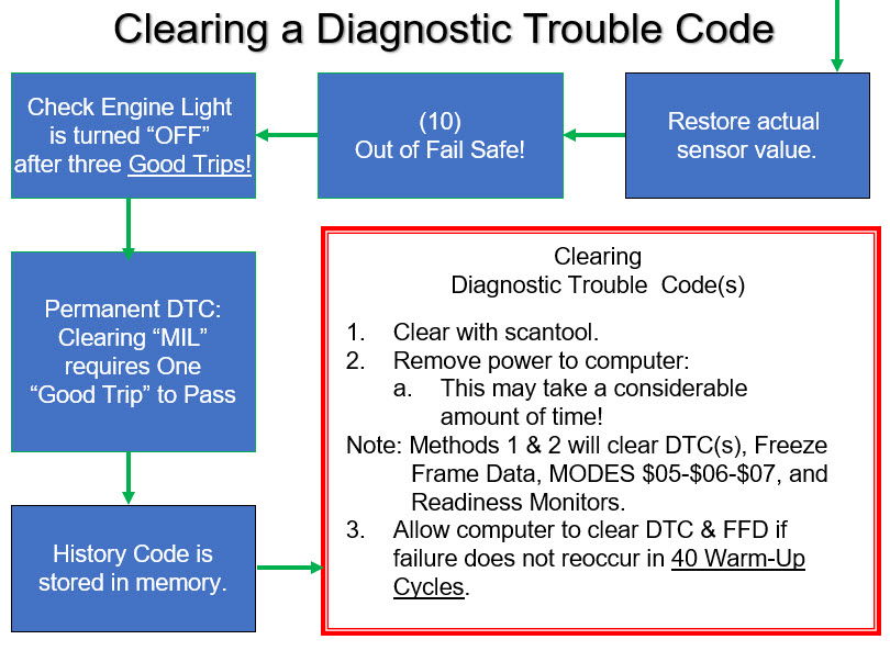
$04 Clear/Reset Emission Related Diagnostic Information
This MODE allows for the clearing and resetting of all DTCs (MODE $03), freeze frame data (MODE $02), readiness flag results (MODE $01), and test results values (MODEs $05 & $06).
When attempting to perform a Clearing of Diagnostic information, the Technician will always be asked: Do you wish to Continue?
The reason is that you may be clearing information that could help diagnose the problem. Or clearing the Readiness Flags could cause someone to fail a Smog Inspection.
MODE $04 does not clear learned or adaptive strategies.
$05 Oxygen Sensor Monitoring Test Results
MODE $05 - Oxygen Sensor Test Results
MODE $05 reports the latest Monitor Test results for the Oxygen Sensors. It is not “live” data. It is stored in memory and replaced with newer test results. The problem with this MODE is that not all manufacturers supported MODE $05. Also, this MODE did not allow the addition of Air Fuel Sensors.
Under CAN Regulations, MODE $05 was eliminated and moved to MODE $06.
MORE CONTENT TO BE ADDED, PLEASE CHECK BACK!

$06 Non-Continuous/Continuous Monitor Test Results
MODE $06 Introduction
MODE $06 is one of 15 modes available to Global OBD II. It provides monitor test results for non-continuous monitors and sometimes continuous monitors. MODE $06 requests the ECM to view monitor test results reported after the test runs.
The ECM compares test results to the limits and reports a Pass or Fail result to the scan tool for each monitored system and component. This MODE will report results in one trip if the monitor runs. They’re stored and are not live values.
How can it help diagnose vehicle emission-related concerns? MODE $06 monitor test results can help confirm the success of repairs for a non-continuous. MODE $06 test values (and pending DTCs) are available to the technician on a two-trip monitor’s first trip. MODE $06 test results can indicate if a monitored system (component) is close to failing a monitor test.
MODE $06 Terminology
Pre-CAN Systems:
- TID = Test Identification – The system (EVAP, CAT, O2, EGR, etc.) being tested.
- CID = Component Identification – The component or area of the system being tested. It is no longer used for CAN MODE $06.
The problem with pre-CAN MODE $06 was that TID/CID was not standardized. The following chart shows the TID/CID for a Toyota/Lexus. These numbers will be completely different when looking at other manufacturers.

CAN "C" Equipped Systems:
- MID = Monitor Identification: The non-continuous system (EVAP, CAT, O2, EGR, VVT, AIR) or continuous system (Misfire, Fuel system, etc.) being tested.
- TID = Test Identification – Specific monitor test being tested.
The chart shown below identifies MIDS for CAN "C" systems. Regardless of the manufacturer, these MIDS are standardized for all vehicles. Some scan tools will report them by MID and not use the Monitor ID name. Some scan tools will report them using the MID and the Monitor name. Regardless, this chart applies to all CAN "C" vehicles.

RELATED TERMINOLOGY:
- Test Limit Type: To pass a test, the value must be either a minimum or maximum value (or between a min/max value)
- Hexadecimal ($): Numeric/Alpha unit that indicates a specific TID/CID or test value (Example: $02)
- Raw Data: Test data in a decimal number indicates the actual test results.
- Manufacturer’s Conversion: A value supplied by the manufacturer to convert this data to values that can be used to diagnose a system (volts, Ohms, amps, inches of mercury, etc.).
- Test Value: = Actual test results.
- Test Result: = Indicates whether the system/component passed or failed a test.
MODE $06 Reporting Formats
Pre-CAN systems: Here is how the PCM and Scan Tool report the Test Results.
Step 1: The PCM communicates in Hexadecimal, a combination of numbers and letters.
Step 2: The Scan Tool reports the results in Decimal format. It does not show the test's name or the result's actual values.
Step 3: The scan tool reports the monitor test name and unit value. Before CAN, this required using a manufacturer’s scan tool because unit conversion numbers differed. There was no way for an aftermarket scan tool manufacturer to keep up with the changes.


MORE CONTENT TO BE ADDED; PLEASE CHECK BACK!

$07 Two Trip Pending Diagnostic Trouble Code
For most OBD II strategies, the same malfunction must occur on two driving events to illuminate the MIL. This “double” detection ensures a malfunction exists before alerting the owner. The first time a malfunction is detected, a “pending” fault code, which identifies the failing component or system, is stored in the onboard computer. If the same malfunction is again detected the next time the vehicle is operated, the MIL is illuminated, and a “confirmed” fault code is stored. When the MIL is illuminated (alerting the vehicle operator to a problem), and a vehicle is brought in for service, a technician uses the “confirmed” fault code to determine what system or component has failed. A “pending” fault code, however, can be used by service technicians to help diagnose intermittent problems and verify that repairs were successful. In these instances, a technician can use the “pending” fault code as a quicker, earlier warning of a suspected (but as yet unconfirmed) problem.


MORE CONTENT TO BE ADDED, PLEASE CHECK BACK!

$08 Request Control of Onboard Component
This MODE enables the scan tool to request the PCM to command the EVAP Vent On.
MORE CONTENT TO BE ADDED, PLEASE CHECK BACK!

$0a Permanent Diagnostic Trouble Code (PDTC)
Any confirmed DTC currently commanding the MIL On can set a Permanent Diagnostic Troubles Code (PDTC). They first appeared in 2010 as part of a three-year phase-in period. By the 2012 model year, all vehicles could set a PDTC. The ECM must have enough memory to store a minimum of four permanent DTCs.
The following capture is an example of the three possible DTCs: a Pending DTC (MODE $07), a stored DTC (MODE $03), and a Permanent Diagnostic Trouble Code (MODE $0a). Note: This capture is from an AUTEL scan tool, which does not display MODEs using Hexadecimal symbols.

A PDTC (MODE $0a) will remain in memory after a stored DTC (MODE $03) is erased. This prevents someone from clearing a DTC before going for a state emissions test. This prevents a vehicle that would typically fail from passing. PDTCs are stored in a non-volatile RAM (NVRAM) to prevent them from being erased with the scan tool or by removing battery power from the ECM.
A PDTC can only be erased from memory if the OBD system extinguishes the MIL (e.g., when the current DTC changes to a History DTC). If the memory is not cleared with a scan tool, the ECM must see the related monitor test complete and pass on three consecutive trips. The PDTC will not be removed from memory until the fourth key-on cycle. If the memory is cleared with the scan tool, the MIL will be extinguished; the MODE $03 (Confirmed DTC) and MODE $02 (FFD) will be cleared. The PDTC will still be in memory, but it will take only one good trip and a second key-on cycle to remove it from memory.
If multiple PDTCs are present, clearing them from memory could take many trips and miles. If the stored MODE $03 DTC is no longer present, this should not affect driveability or emissions. Clearing a Permanent Diagnostic Trouble Code was initially complicated. Eventually, these issues were resolved by reprogramming the ECM. If a reflash update is designed to fix a PDTC issue, the PDTC will be erased during the update. If the reflash is unrelated to the PDTC, the update cannot erase it.
For a Misfire and Fuel System PDTC, the ECM must support storing up to four similar conditions window (SCW) in NVRAM to allow proper clearing from memory. If a Misfire of Fuel System PDTC is stored during the first occurrence, the ECM must store an SCW that includes engine speed +/- 375 rpm, engine load +/-20 %, and the same warmup condition below 160°F or 160°F and above. The SCW allows the ECM to monitor the specific Misfire/Fuel system conditions when the DTC was initially set. If additional Misfire or Fuel System DTCs are specified, each must store a SCW.
Think of an SCW as a freeze frame set in memory when a Pending DTC (MODE $07) is set for a misfire or fuel system problem. It gives the ECM the window of information it needs to monitor a recurrence under the same driving conditions. The technician cannot view this information when a Pending DTC is present. If a second failure and a confirmed DTC is set in the same window, the MIL will be ON, and a reviewable freeze frame will be stored in MODE $02. Now, the technician can review the conditions that set the DTC through the freeze frame data (FFD).
Chrysler is the only manufacturer that provides this information through its factory scan tool. The following two captures demonstrate Similar Conditions Windows (SCW).

For Smog Inspectors in California, pay attention to Warmup cycles and Miles Driven. PID $30 (Warm-up Cycles Since Cleared) and PID $31 (Distance Traveled Since Cleared) are used by the OIS to Pass or Fail a vehicle with a PDTC(s). If the Warm-Up Cycles are 14 or less or the Distance Traveled is less than 200 miles, the OIS will fail the vehicle. If the Warm-Up Cycle counter is => 15 and the Distance Traveled is => 200 miles, the OIS will ignore the PDTC and pass this inspection portion.

For 2010MY and newer, the California Air Resources Board (CARB) created a universal drive cycle pattern for clearing misfire and fuel systems DTCs. Before this type of PDTC can be erased, Cumulative time since engine start must be 600 seconds; Cumulative vehicle operation at or above 25 miles per hour equal to 300 seconds (medium-duty vehicles with diesel engines certified on an engine dynamometer may use cumulative operation at or above 15% calculated load instead of the 25 miles per hour); and Continuous vehicle operation at idle (i.e., accelerator pedal released by driver and vehicle speed less than or equal to one mile per hour) for greater than or equal to 30 seconds. Then, the ignition must be turned off for at least five seconds and then cycled on again.

The California Smog Check Program is the only state that uses Permanent Diagnostic Trouble Codes to fail a vehicle. There are some exemptions to this rule, and they can be found at On-Board Diagnostic Test Reference - Bureau of Automotive Repair.
BMW Pattern
1. This pattern should be used for most BMW vehicles. The differences within this pattern are the methods of EVAP Leak Detection. After a cold soak start, the system will test if it has a leak detection pump (LDP). If it has a Natural Vacuum Leak Detection (NVLD) or Diagnostic Module Tank Leakage (DMTL) pump, EVAP Small Leak monitor tests will run after an extended engine-off time.
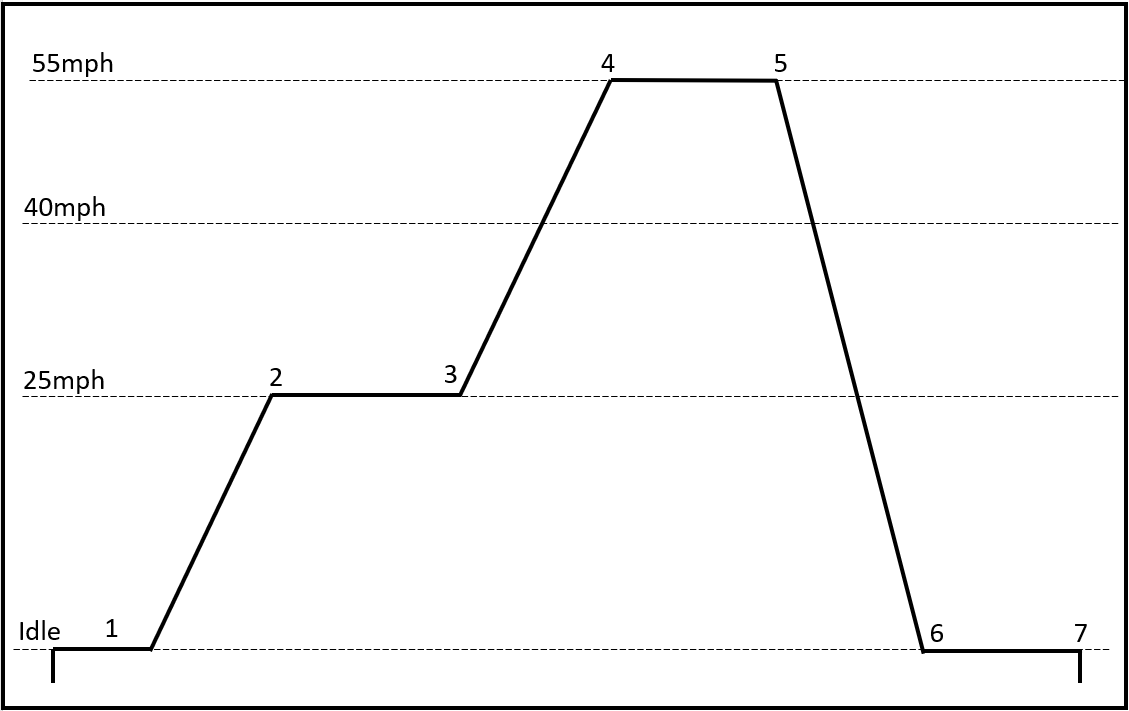
2. The procedure listed pertains to the pattern shown above. NOTE: These steps can run out of order depending on the vehicle speed and engine load.

Chrysler/Dodge Pattern 1 - pre-CAN
Topics in this section include:
- Drive Cycle Pattern 1
- Drive Cycle Procedures
- Drive Cycle Video
1. This pattern should be used for most 1996-2007 Chrysler and Dodge vehicles. The differences within this pattern are the methods of EVAP Leak Detection. The system will test after a cold soak start if it has a leak detection pump (LDP). If it has a Natural Vacuum Leak Detection (NVLD) or EVAP System Integrity Module (ESIM) switch, it will test after the end is shut off.

2. The procedure listed pertains to the pattern shown above. NOTE: These steps can run out of order depending on the vehicle speed and engine load.

3. The video was captured while performing the drive cycle on a dynamometer. The factory scan tool was used to display the inner workings of the Engine Control Module (ECM). Note: The enable criteria are shown on the scan tool at the top of each screen. The readiness flag status for this drive cycle is displayed in the middle of the screen.
Ford Pattern 1


Ford Pattern 2
This drive cycle has been used for many FORD vehicles since 1998. One important note is that it does not mention the O2 Sensor monitor test. Experience has proven that O2 heaters and O2 readiness flags work together. The O2 heater must run and pass before the O2 monitor test will run and flip the readiness flag to Complete!
Note: for Ford vehicles equipped with Universal Exhaust Gas Sensors (UEGO), a variation of the HEGO step listed below is required. This is covered later in this section.
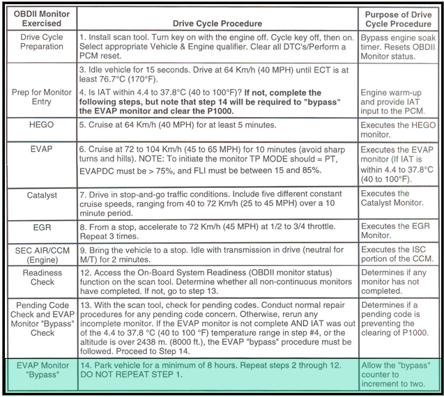
Some Ford products have an EVAP Monitor Cold Soak Bypass Timer. An internal timer in the ECM determines Cold Soak. If available, it will be displayed on the OEM side of the scan tool under Current Data/Emissions. If the status is YES, the vehicle has sat long enough to achieve a Cold Soak, allowing the EVAP monitor test to run if the fuel level is correct. If it says No, it is not ready, but it can be bypassed. To Bypass the EVAP Monitor Soak Time Command, turn the key on with the engine off and perform a MODE $04 Diagnostic Clear, but do not turn the key off. The Cold Soak Bypass Timer will switch from NO to YES. After clearing the information, do not turn the key off; start the engine and follow the abovementioned steps. It is now ready to run the EVAP monitor tests, allowing other monitor's tests to run, providing their enable criteria are met.
The Cold Soak Bypass timer is not available on all Ford vehicles. The only way to be sure is to check the emissions page through the enhanced side of the scan tool.
General Motors Pattern 1 - Cruise CAT Monitor
Topics in this section include:
- Drive Cycle Pattern 1
- Drive Cycle Procedures
- Drive Cycle Catalyst Monitor without EVAP video
- Drive Cycle EGR Monitor under deceleration video
- Drive Cycle EVAP 0.040" Monitor at cruise video
1. This pattern should be used for many GM vehicles starting in 1996. It represents the vehicles that run the Catalyst monitor tests at cruise. It is possible to run the vehicle at a steady cruise to complete the Oxygen sensor and Catalyst monitor tests first and then run the EGR monitor tests.
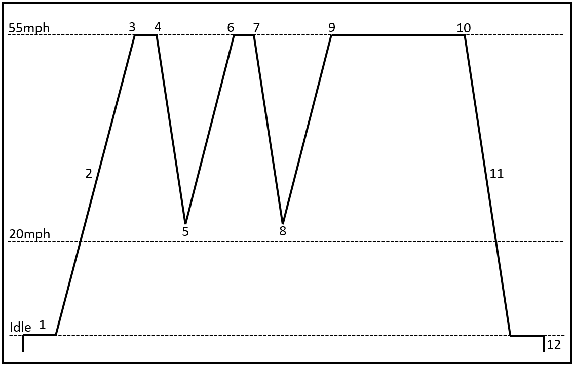
2. The steps listed pertain to the pattern shown above. NOTE: Depending on the startup engine temperature, vehicle speed, and engine load, these steps can run out of order.

3. This video shows the Catalyst monitor tests running to completion at cruise in steps 9 - 10 in the above pattern. If the O2 or CAT readiness flag(s) is the only flag(s) not set, warm up the engine and follow this part of the pattern. It was edited to exclude a couple of minutes of steady cruise. Note: Some enable criteria are shown on the scan tool at the top of the screen. The readiness flag status for this drive cycle is not displayed on the screen.
4. This video shows the EGR monitor tests running to completion after multiple decelerations. If the EGR readiness flag is not set, warm up the engine and follow steps 1 - 8 in the above pattern. While watching the video, look closely at the PIDs used to count EGR samples. When the vehicle is accelerating, the system is in non-readiness mode. When the vehicle is decelerating, the system is in readiness mode. Note: Some enable criteria are shown on the scan tool screen. The readiness flag status for this drive cycle is not displayed on the screen.
5. This video shows the EVAP 0.040" monitor tests running to completion at steady cruise after a Cold Soak startup. While watching the video, look closely at the PIDs used to monitor the system for leaks. Note: The actual monitor test is being performed, and the test result is displayed in the middle of the screen below the PIDs. The readiness flag status for this drive cycle is not displayed on the screen.
General Motors Pattern 2 - Idle CAT Monitor
Topics in this section include:
- Drive Cycle Pattern 2
- Drive Cycle Procedures
- Drive Cycle Catalyst Idle at cruise video
- Drive Cycle EGR Monitor under deceleration video
- Drive Cycle EVAP 0.040" Monitor at cruise video
- Drive Cycle EVAP 0.020" Engine Off Natural Vacuum (EONV) Monitor video
1. This pattern should be used for many GM vehicles starting in 1998. It represents a vehicle that runs the Catalyst monitor tests at idle step 12. It is possible to run the vehicle at a steady cruise to complete the Oxygen sensor and Catalyst monitor tests first and then run the EGR monitor tests.

2. The steps listed pertain to the pattern shown above. NOTE: Depending on the startup engine temperature, vehicle speed, and engine load, these steps can run out of order.

3. This video shows the GM Idle Catalyst monitor test running to completion at idle. It is recommended that full screen be selected for better video quality and clarity. The readiness flag status for this drive cycle is not displayed on the screen.
4. This video shows the EGR Decel monitor tests running to completion after multiple decelerations. If the EGR readiness flag is not set, warm up the engine and follow this part of the pattern. While watching the video, look closely at the PIDs used to count EGR samples. Note: Some enable criteria are shown on the scan tool screen.
The following capture shows the GM CAT monitor test running idle. This data was collected through Global OBDII on a CAN-compliant vehicle.

This data was collected through Global OBDII on a CAN-compliant vehicle.
Step 1: The PCM Commands a Lean-to-Rich A/F ratio; the A/F ratio is quickly changed from a Lean Command to Lambda and then to a Rich Command.
Step 2: The system is now in an Open Loop, with no O2 Sensor Feedback Correction through Fuel Trims.
Steps 3 & 5: The front O2s Sensors respond by indicating a Lean exhaust as the Commanded A/F ratio moves to a Lean A/F ratio, and the front O2 Sensors respond by showing a Rich Exhaust Condition as the A/F ratio moves to a Rich Command.
Steps 4 & 6: The rear O2 Sensors respond by indicating excess oxygen exiting the CAT. As the A/F ratio command moves Rich, the CAT is slowly depleted of Oxygen, raising the rear O2 Sensor’s voltages.
The CAT Monitor has now been Completed because no DTC is present. MODE $06 test results showed both CATs passing within the Min/Max Parameters. If you understand the enable criteria and the PIDs available, you can set up a custom screen to watch the operation of some monitor tests as they run.
5. This video shows the EVAP 0.040" monitor tests running to completion at steady cruise after a Cold Soak startup. While watching the video, look closely at the PIDs used to monitor the system for leaks. Note: Some enable criteria are shown on the scan tool screen. The actual monitor test is displayed in the middle of the screen.
6. This scan tool graphing video shows the EVAP 0.020" very small leak monitor tests running to completion with the engine-off.
Honda/Acura Pattern 1

Nissan/INFINITI Pattern 1 - Early EVAP System
Topics in this section include:
- Drive Cycle Pattern
- Drive Cycle Procedures
- Drive Cycle Video without EVAP
- Drive Cycle EVAP Video
1. This pattern should be used for most NISSAN/INFINITI vehicles between 1998 - 2003. During these years, the EVAP system tested under pressure in Steps 5 & 6.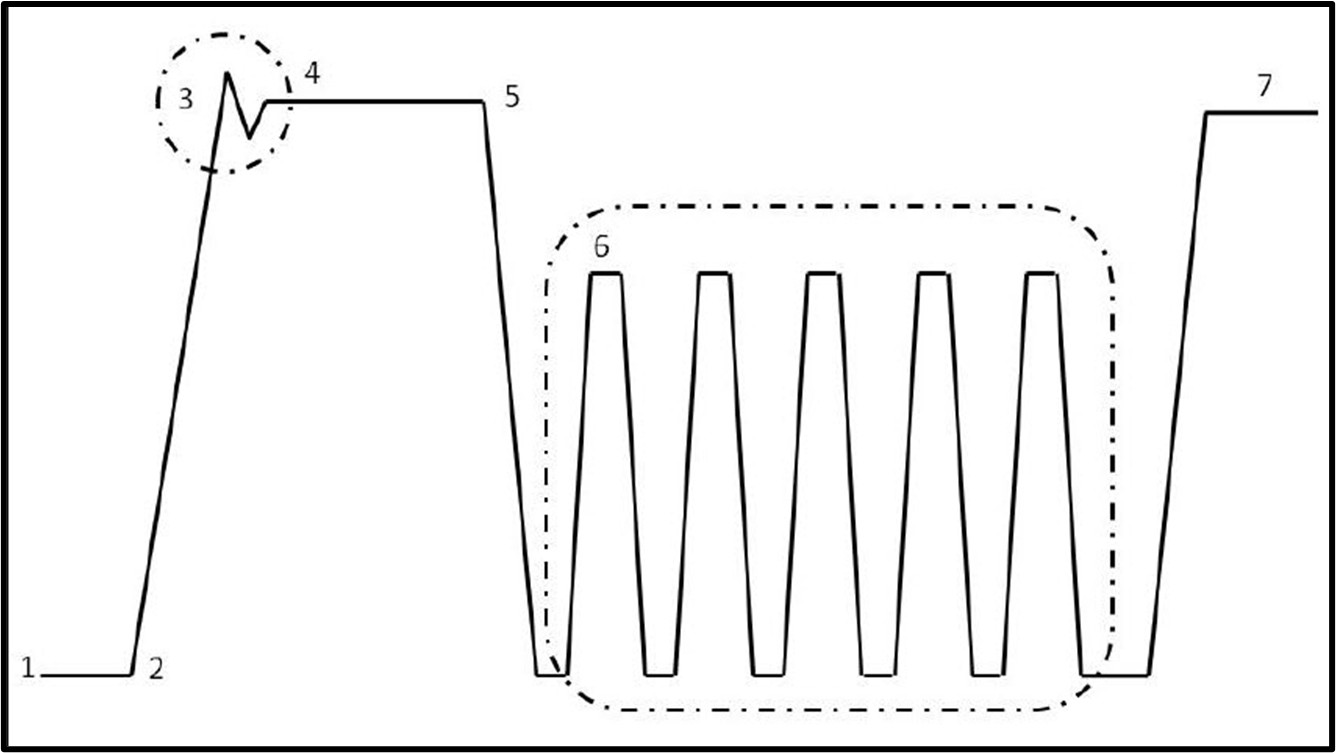
2. The steps listed pertain to the pattern shown above. NOTE: Depending on the startup engine temperature, vehicle speed, and engine load, these steps can run out of order.

3. This video was captured while performing this drive cycle on a dynamometer. The factory scan tool at that time displayed the inner workings of the Engine Control Module (ECM). Pattern 1 does not show Steps 5 & 6 for the EVAP portion of the drive cycle. These steps will be shown in the following video.
4. This video shows NISSAN Pattern 1 Step 5. Step 6 is only required if the Fuel Temp Sensor does not rise at least 2 degrees Celsius (4 degrees F). Focus on the Fuel Tank Temperature, Purge VOL, VAC Cut, and Vent solenoids. The OE side of the scan tool will have to be accessed to see these PIDs. NOTE: The vent solenoid might not be displayed when using an aftermarket scan tool.
Nissan/Infiniti Pattern 2 - Late EVAP System
Topics in this section include:
- Drive Cycle Pattern
- Drive Cycle Procedures
- Drive Cycle without EVAP Video
- Drive Cycle EVAP Video
1. This pattern was used for most NISSAN/INFINITI between 2004 & later vehicles. The EVAP system will be tested under a vacuum in Steps 4 & 5 during these years. If the Fuel Tank Temperature Sensor indicates the fuel tank temperature has not increased enough, step 6 must be performed.

2. The steps listed pertain to the pattern shown above. NOTE: Depending on the startup engine temperature, vehicle speed, and engine load, these steps can run out of order.

3. This video was captured while performing the drive cycle on a dynamometer. The factory scan tool at that time displayed the inner workings of the Engine Control Module (ECM). NISSAN Pattern 2 was used for most NISSAN/INFINITI vehicles after 1998. The main difference after 2003 was with the EVAP system. The video does not show Steps 5 & 6 in Pattern 2. Those steps will be shown in the following video.
4. This video shows NISSAN Pattern Steps 4 - 5. Step 6 is only required if the Fuel Temp Sensor does not rise a minimum of 4⁰ F (2⁰ C). Performing step 6 multiple times will slosh the fuel in the tank, increasing temperature and pressure. Focus your attention on the Purge VOL and Vent solenoids. This system leaks, so the PCM first tests the system using vacuum decay and then proceeds to test the system under pressure.
Nissan/Infiniti in-bay CAT Monitor
This capture is a cold start, and this leads to running the non-continuous monitor tests. The test took longer to run due to the cold startup temperature. All tests completed, except for EVAP. Not all PIDs are graphed, but their values are displayed to the left. Use your mouse to control video playback. Take note of the blue bar graph and where the tests were completed.
This capture is a hot restart, leading to running the non-continuous monitor tests. All tests completed, except for EVAP. The test ran faster due to the startup temperature. Not all PIDs are graphed, but their values are displayed to the left. Use your mouse to control video playback. Take note of the blue bar graph and where the tests were completed.
These two captures show how the order and timing of the drive cycle can change depending on the startup temperature and how the vehicle is driven. Do not get lost in a drive-cycle pattern; look for the window where the criteria are met.
Toyota/Lexus Pattern 1 - Non-Intrusive EVAP
Topics in this section include:
- Drive Cycle Pattern
- Drive Cycle Procedures
- Drive Cycle without EVAP video
- Drive Cycle non-Intrusive EVAP video
1. This pattern should be used for 1996-2000 Toyota and Lexus vehicles. These vehicles were equipped with a non-Intrusive Evaporative Emission System.

2. The steps listed pertain to the pattern shown above. NOTE: Depending on the startup engine temperature, vehicle speed, and engine load, these steps can run out of order.

3. This video was captured while performing the drive cycle on a dynamometer. The factory scan tool at that time displayed the inner workings of the Engine Control Module (ECM).
4. This video shows the non-Intrusive EVAP monitor tests running to completion at steady cruise after a Cold Soak startup. While watching the video, look closely at the PIDs (Purge, Vapor Pressure, and Vapor Pressure Solenoid); they monitor the system for leaks. Note: The readiness flag status for this drive cycle is displayed at the bottom of the screen.
Toyota/Lexus Pattern 2 - Intrusive EVAP System
Topics in this section include:
- Drive Cycle Pattern
- Drive Cycle Procedures
- Drive Cycle without EVAP video
- Drive Cycle Intrusive EVAP video
1. This pattern should be used for 2001 and newer Toyota and Lexus vehicles. These vehicles were equipped with an Intrusive or Vacuum Pump Evaporative Emission System.

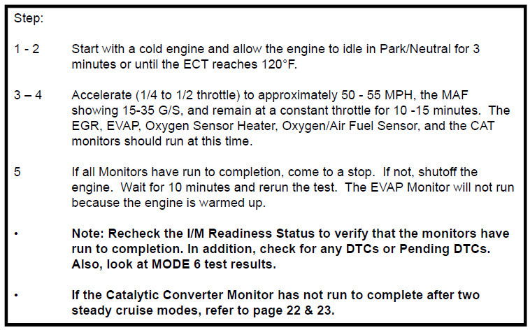
Toyota Late Model V6 Drive Cycle
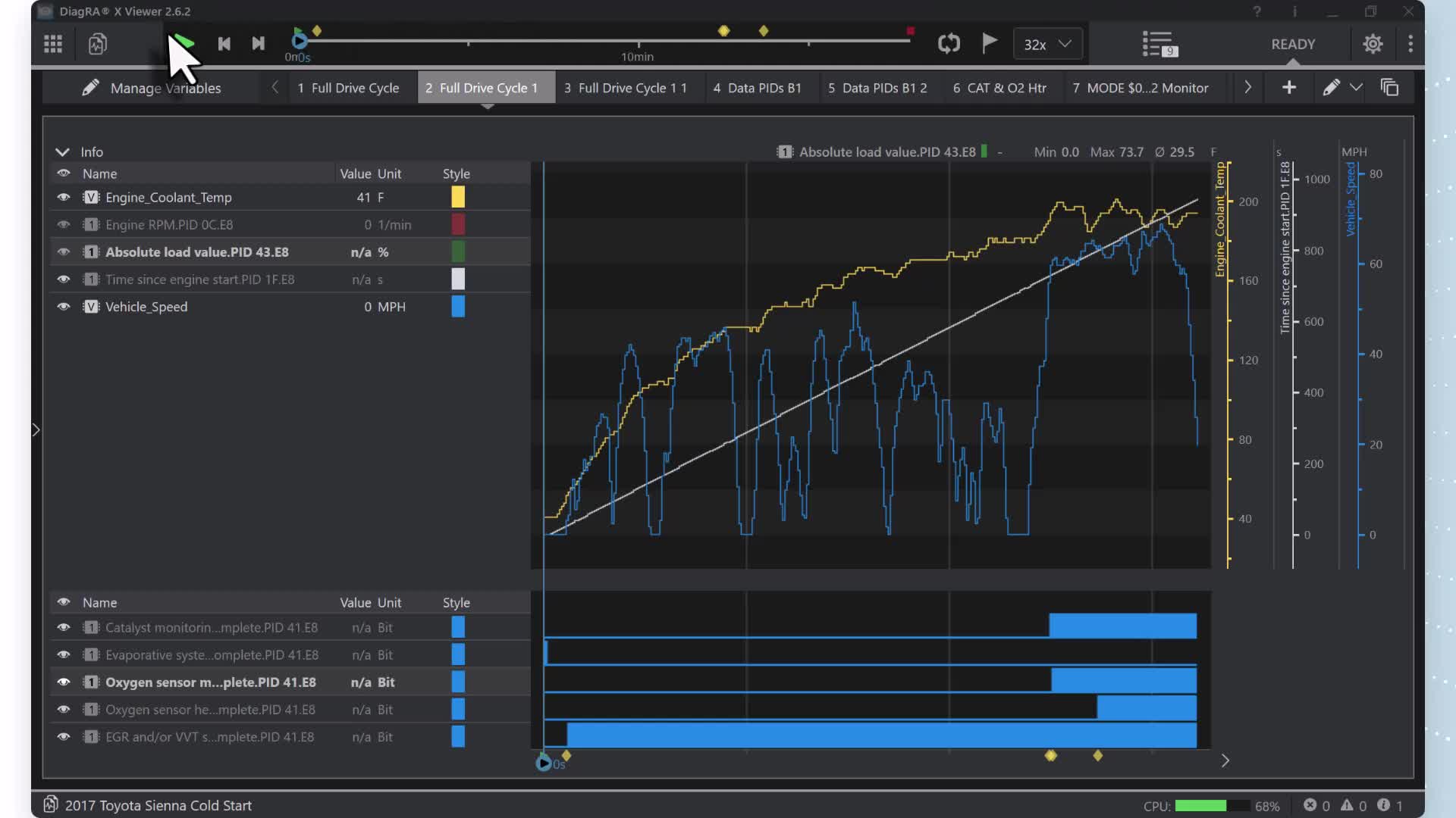
This capture is a cold start, and this leads to running the non-continuous monitor tests. The test took longer to run due to the cold startup temperature. All tests completed, except for EVAP. Not all PIDs are graphed, but their values are displayed to the left. Use your mouse to control video playback. Take note of the blue bar graph and where the tests were completed.
This capture is a hot restart, leading to running the non-continuous monitor tests. All tests completed, except for EVAP. The test ran faster due to the startup temperature. Not all PIDs are graphed, but their values are displayed to the left. Use your mouse to control video playback. Take note of the blue bar graph and where the tests were completed.
These two captures show how the order and timing of the drive cycle can change depending on the startup temperature and how the vehicle is driven. Do not get lost in a drive-cycle pattern; look for the window where the criteria are met.
Individual Monitor Patterns
This section will address some oddities when performing individual monitor tests, separate from running a complete drive cycle.
MORE CONTENT TO BE ADDED; PLEASE CHECK BACK!


CASE Study (FORD PTO Mode)
I received a text from a student/tech working in a fleet shop. A 2011 Ford E350 5.4L with a total of 6500 miles. Yes, only six thousand miles. It’s a fleet vehicle. The smog inspection failed because none of the monitors were completed. So, they drove around and put in a few hundred miles, but not even one monitor was completed. Then they replaced the PCM program “as built” and put in another few hundred miles, and the same thing happened: none of the monitors were completed.
So, they sent it to me and asked for help. I scanned the computer, and no-fault codes were set. I checked Mode $06, and all monitors were enabled to “yes,” so I drove it a couple hundred miles. None of the monitors were completed. I checked Mode $09, and all monitors had never been run, not even one condition or completion.
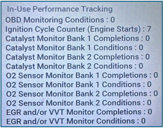
My Response to the student/tech. Have you checked the Power Take-Off Mode? While PTO mode is engaged, the I/M readiness bits are set to a “not-ready” condition. When PTO mode disengages, the I/M readiness bits are restored to their previous states before PTO engagement. During PTO mode, only CCM circuit checks continue to be performed. Thank you so much for the info, Rick. What is the PTO mode? (Power Take-Off?)
My Response to the student/tech. Auxiliary equipment called power take-off, or PTO, is often added to the engine or transmission to operate utility equipment. Examples include a wheel lift for tow trucks, cranes, construction or tire service tools, and pumping fluids. PTO applications draw auxiliary horsepower from the powertrain, often while the vehicle is stationary. In this condition, limited cooling airflow through the radiator and around the vehicle generally occurs when a vehicle is moving. The aftermarket PTO system installer, having the most knowledge of the final application, is responsible for determining whether additional chassis heat protection or powertrain cooling is required, and alerting the user to the safe and proper operation.
Hi Rick, Thank you so much for your help and the information about the PTO. I finally got some time today to do it, and the truck is fixed. I disconnected all the wires from the PTO to the ignition switch and reset the PCM keep-alive memory. I drove the truck for 15 minutes and completed all the monitors except for the EVAP. I think that was because the tank was full.
Tackling Incomplete Readiness Flags and Monitor Tests
This section will cover the following topics:
- Define the differences between a readiness flag and a monitor test.
- Present a driver-seat diagnostic plan for handling incomplete readiness flags for non-continuous monitor tests!
- Define In-Use Monitor Performance Tracking (IUMPT) Numerator (Completions), Denominator (Conditions), and Numerator/Denominator Ratio.
- Develop an understanding of how GLOBAL OBDII MODES, MODE $09 & MODE $06, can be used to identify why a Readiness Flag won’t Flip to Complete.
- Discuss a variety of case studies that apply the techniques covered in this workshop.
What is the difference between a readiness flag and a monitor test?
A readiness flag reports that a specific emission-related system has completed testing. Each readiness flag can consist of one or multiple individual monitor tests. State emissions programs use some readiness flags as part of an official Inspection, and a minimum number of readiness flags must be Completed to pass the Inspection.
Non-continuous readiness flags can only flip to complete “Once Per Trip” when the enable criteria are met for the following:
- Catalyst(s)
- Oxygen & Air Fuel Sensor(s)
- Heated Oxygen & Air Fuel Sensor(s)
- EGR and VVT
- Evaporative Emissions
- Secondary Air Injection
A system-specific Monitor test can set a Diagnostic Trouble Code (DTC). It should not be associated with only readiness flag status because every DTC has a related monitor test used to pass or fail a system or component. A monitor test applies to both non-continuous and continuous monitor testing.
The following capture shows a non-continuous monitor test that will run once per trip if it passes. If it is marginal or failing, the ECM will run the test multiple times during the same trip. So, non-continuous readiness flag tests can only be completed once per trip, but the monitor test can run multiple times if it fails.

The following plan is a driver-seat diagnostic approach to handling incomplete readiness flags for non-continuous monitor tests.
The most common response from a technician preparing the vehicle for an emissions inspection is, "I can't get the monitors to run." The better response should be, "I can't get the ............flag to complete." Once the technician understands this, an organized, systematic driver-seat approach is needed.
Here is a plan to help organize that systematic approach. The chart can be used on almost all OBD II vehicles. The box below for In-Use Monitor Performance Tracking (IUMPT) provides a history to identify a problematic readiness flag. This should be considered when quoting a price to run and set one or more readiness flags.
As you move through this chart, note the vehicle's year and how many readiness flags are set to Not Complete.

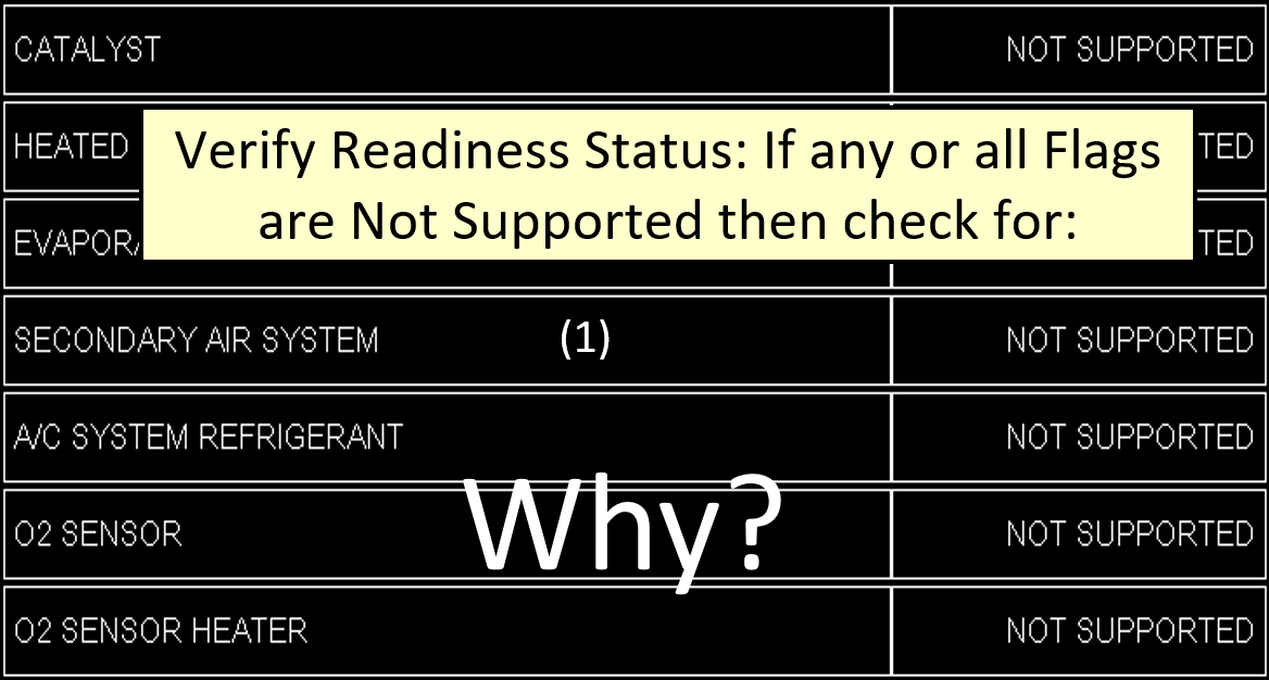
Begin by verifying the readiness flag status in MODE $01 for Monitors Since DTCs Last Cleared. The following capture is a red flag that Modified Software was installed because all readiness flags have been disabled and reported as unsupported. This vehicle has most likely been tuned with an aftermarket tuner, and the readiness flags have been disabled.
The following capture could have occurred because the memory cleared, the vehicle had been driven such that no enable criteria were met, and more driving was required. It could also be the battery died, the Keep-Alive Memory to the ECM lost power was removed, or the ECM was reprogrammed.

This indicates another approach is required because the O2 Sensor is the only readiness flag needed to pass the Smog Inspection. This could pose a problem and cost time and money.

The following will define In-Use Monitor Performance Tracking Completions, Conditions, and Ratios.
For CAN “C” equipped vehicles, check MODE $09, In-Use Monitor Performance Tracking (IUMPT), to see the frequency with which each readiness flag runs. This information might be found on some 2007 model-year vehicles with ISO 9141 and J1850 protocols. IUMPT can provide valuable information about the success rate for setting each readiness flag.

The word "Numerator" identifies the Completions. It represents the actual monitoring events where the OEM enable criteria ran long enough that a malfunctioning component or system would have been detected. Regardless of whether the readiness flag passes or Fails, the Numerator will be incremented. The Numerator alone does not indicate the chances of completing a readiness flag or flags.

The word Denominator identifies the Conditions. It represents the number of times the manufacturer has met the CARB criteria and been charged with a trip. Meeting CARB criteria establishes a charged trip against the manufacturer. Understand that the Denominator is a measure of vehicle driving activity; it is not a measure of actual monitoring opportunities. The Denominator alone does not indicate the chances of completing a readiness flag or flags.

Knowing the Completions and Conditions creates an In-Use Monitor Performance Track Ratio (IUMPR). This ratio allows CARB to track the frequency of a readiness flag monitor test that runs long enough to detect a failing component or system. Understanding this ratio can be invaluable for the technician when identifying difficult-to-complete readiness flags.

CARB established the minimum in-use ratios below for 2010 and newer vehicles. During the phase-in years of 2007-2009, the In-Use Monitor Performance Ratio (IUMPR) requirements were 0.100 for all tracked readiness flags. These are the minimum acceptable ratios established by CARB but unacceptable for the technician. The ratio displayed in MODE $09 on the vehicle gives the technician an idea of the chances of completing a readiness flag or flags.
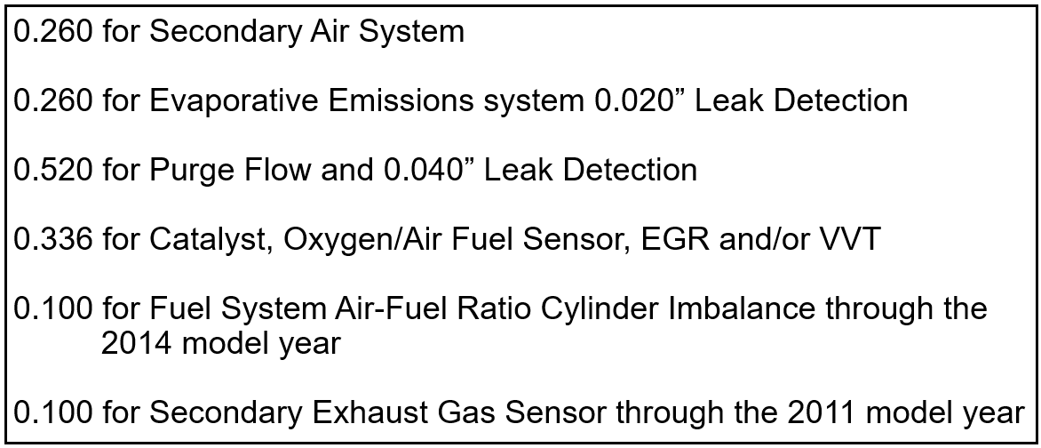
The following capture is from a vehicle equipped with a 0.040” EVAP leak detection monitor test. The minimum CARB ratio for a 0.040” EVAP leak detection monitor test is .520 (0.40” Leak). This particular vehicle is well below the minimum acceptable ratio.

What is the Definition of a CARB Denominator Trip?
The Catalyst, O2 Sensors, EGR, and VVT Denominators should be incremented only on trips that meet the following CARB Criteria:
- The total Propulsion time for the current trip is >/= 10 minutes,
- Total run time above 25mph during the current trip is >/= 5 mins,
- One continuous idle during the current trip is >/= 30 seconds,
- The elevation is < 8000 feet,
- Ambient Temperature is > 20⁰ F.
- Hybrid vehicles, cumulative fueled engine operation >= 10 s
Additional Monitor-Specific CARB Criteria:
- Secondary AIR also requires a 10-second commanded “ON” signal.
- Honda/Acura i-VTEC without EGR: requires both a mid-range (4500 Rpm) and full-range (>6200) commanded "ON" signal.
- At startup, EVAP requires ECT and IAT temperatures to be within approximately 10°F of each other. The ECT temperature must be between 40°- 95°F.
- If the above conditions are not met, then a CARB Trip is not charged against the manufacturer.
The CARB Trip is comprised of three tests:
- Total Propulsion Time =10 minutes.
- One continuous 30-second idle.
- 5 minutes of accumulated drive time above 25mph.
Only one CARB trip per readiness flag can occur per key cycle!

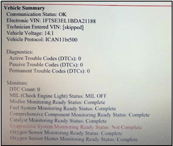
The following capture shows In-Use Monitor Performance Tracking data. The OBD Monitoring Conditions 745 matches the Catalyst, O2 Sensor, EGR/VVT, and Secondary O2 Sensor conditions. While this will not always be the case, they will typically be close.

One readiness flag is not shown in the previous capture; the O2 Heater is omitted. Why not? CARB does not see it as that critical because it is not calibrated to an emission threshold (like a heater performance fault before emissions exceed 1.5x standards); it is just a functional check: is the heater working or not working?
In the following capture, note that the Numerators and Denominators incremented for the Catalyst, O2 Sensors, and EGR/VVT. Assuming all monitor tests have passed, it is safe if no DTC is present. This shows what happens when an OEM and CARB trip is complete in the same key cycle. The EVAP numerator and denominator remained unchanged, indicating they did not meet the OEM or CARB trip definition.
Note: IUMPT will not increment until the key is turned off long enough to end the previous trip; it will update at the next key-on cycle.

The vehicle in the following capture was equipped with a Key-Off EVAP system. After the key was turned off, the vehicle sat long enough to allow the Key-Off EVAP monitor tests to run and increment the Completions during an OEM trip that did not meet the criteria for a CARB trip. The manufacturer was not charged for a CARB trip, so the Numerator Increased without the Denominator Increasing.

The following capture shows the completions for the O2 and EGR increments during many OEM trips that did not meet the criteria of the CARB trip. This could happen for the following reasons:
- The vehicle is in excellent working order, and the enable criteria are easily met, so readiness flag monitor tests are completed more frequently without meeting the requirements for a CARB trip.
- The vehicle could be in an Exponentially Weighted Moving Average (EWMA) MODE that requires multiple trips. During these trips, the Numerator will increment when the required monitor test runs long enough to detect a Pass/Fail.
Why didn’t the Denominator increment? An example would be starting the vehicle and immediately accelerating to 55mph while cruising the O2/AFS and CAT monitor test run. The technician immediately stopped and shut off the vehicle after five minutes with only four minutes above 25 mph and no thirty-second continuous idle period. Did this trip meet the definition of a CARB Trip? The answer is No. Look back at the criteria for a CARB trip.
What do these readings tell you about your ability to run these monitor tests? The ratios are well over one, indicating that their readiness flags should be easy to flip to Complete.

The following was captured from Ford OBDII Reference Data for Gasoline or Hybrid vehicles to show what DTC(s) will increment the Numerator. If this specific DTC test runs long enough to determine if the system or component could fail, the Numerator will increment. These DTCs are also considered a "Once Per Trip" monitor test. It should be typical of other manufacturers.

Each DTC relates to an individual monitor test. Multiple monitor tests can pass, and the readiness flag remains Not Complete. The following capture shows all the O2 sensor DTCs available on one vehicle. The "Once Per Trip" DTCs highlighted in Green are the DTCs responsible for flipping the readiness flag to complete.
Learn to quickly scan the MODE $06 MIDs related to pre- and post-oxygen sensors. If any of the TIDs report a Test Result of 0, that is most likely the blocker preventing the readiness flag from flipping to complete. This video demonstrates the technician scanning MODE $06 TIDs because the O2 Sensor flag is incomplete. In this case, it cannot be said that the monitor would not run; many monitor tests have run, but the monitor test required to flip the flag has not run yet.
In this next video, MID $01 and TID $85, shown in the previous video, are now run and passed. The readiness flag is now Complete.
A Review Before the Case Study
- One or more monitor tests are required to flip a readiness flag.
- IUPMT represents a group of monitor tests required to flip a readiness flag.
- Scan through MODE $06 looking for potential blockers.
- A CARB Trip creates a ratio to show that monitor tests are running frequently enough to detect an emissions failure.
- Do not drive a vehicle to complete a CARB Trip unless the pattern is used to clear a PDTC related to a misfire, fuel system, or circuit open or short faults.
- Reasons for CARB Denominator to remain low:
- Individual driving habits or type of vehicle (Diesel or Hybrid or Start-Stop)
- Additional CARB criteria are required for some monitor tests (EVAP, AIR, i-VTEC)
- A confirmed DTC for a related monitor test will suspend the counting of a CARB Trip
- IUPMT might reset after a reflash, depending on where the information is stored.
IUMPT Case Studies
Unified Diagnostic Services
This section will address "E/E Diagnostic Test Modes: Onboard Diagnostics II on Unified Diagnostic Services (OBDonUDS), SAE 1979-2/3. It is a Worldwide Harmonized OBD Vehicle System. This system incorporates SAE J1979-2/3 and ISO 14229 standards.
The most critical information needed to understand SAE 1979-2/3 is a solid understanding of SAE 1979/Global OBDII. Being familiar with the changes introduced by the Controller Area Network (CAN) in 2008 will make the transition easier. These changes included improvements to PIDS (MODE $01), Test Results (MODE $06), Vehicle Information (MODE $09), and Permanent DTCs (MODE $0a). This information can be viewed by clicking on this link.
- What is UDS?
- Implementation
- OBDonUDS Data Enhancements
- SAE J1979 versus SAE J1979-2 Standards
- How will this impact current I/M programs?
1. Unified Diagnostic Services (UDS) is a new software program that will reformat how diagnostic information is displayed using a Generic Scan Tool (GST). It will organize diagnostic services into user-friendly groups and provide more detailed diagnostic information. These new UDS services for OBD will be called “OBDonUDS" and will use SAE J1979-2/3 standards.
It will still use the CAN communications protocol, but the message will have seven layers instead of the current five. It will still use CAN communication (i.e., pins 6 + 14) through the current OBD-II connector (SAE J1962). These vehicles must use SAE J1979-2 for all OBD-II communications and will not respond to currently used protocols. OBDonUDS includes classic J1979 Modes $01 to $0A and features such as DTC-specific Readiness Flag test results and IUMPR to OBD, but they will be referred to Services, not Modes.
SAE 1979-2, OBDonUDS, will include light-duty, medium-duty, and heavy-duty Spark and Compression engines. SAE 1979-3, ZEVonUDS, will cover Zero-Emission Vehicles.
2. Implementation of OBDonUDS is for all LD, MD, HD, and ZEV vehicles. The system will be installed on some 2025/2026 model-year vehicles. The number of vehicles equipped with the services each model year is up to the manufacturers. It is expected that full implementation will occur with the 2027 model-year vehicles.
3. OBDonUDS Data Enhancements will include 1) expanded readiness group categories, 2) redefined readiness completion requirements for misfire, fuel system, and comprehensive components, 3) added DTC status byte to provide DTC-specific readiness and other DTC-specific info (i.e., pending status, confirmed status, and complete this drive cycle), 4) Enhanced freeze frame support to 5 DTCs where each DTC will have two allotted freeze frames (one for the first occurrence and the second for the most recent event), 5) expanded DTC naming to 3 bytes (no longer using 2-byte DTCs), added failure type byte (FTB) to current DTC names to create more DTCs available for use, 6) and added evaporative system (EVAP) sealing functionality.
4. SAE J1979 versus SAE J1979-2/3 Standards Services:
| OBD Functionality | SAE J1979 (OBDII) | SAE 1979-2 (OBDonUDS) |
| Powertrain Data/Readiness Status | MODE $01 | Service $22 |
| Freeze Frame Data | MODE $02 | Service $19/$04 |
| Confirmed DTC | MODE $03 | Service $19/$04 |
| Clear Emissions Data | MODE $04 | Service $14 |
| DTC Test Results | MODE $06 | Service $19/$06 |
| Pending DTCs | MODE $07 | Service $19/$42 |
| Request Control | MODE $08 | Service $31 |
| Vehicle Information (CAL ID and CVN) | MODE $09 | Service $22 |
| DTC In-Use Monitor Performance Ratio (IUMPR) | MODE $09 | Service $19/$06 |
| Permanent DTCs | MODE $0a | Service $19/$55 |
*List of DTCs within each Readiness Group | No Support | Service $19/$56 |
| *List of DTCs that support IUMPR* | No Support | Service $19/$1A/$91 |
| *List of DTCs that support DTC Test Results* | No Support | Service $19/$1A/$92 |
| *Supplemental Monitor Activity Data* | No Support | Service $19/$06 |
*New to OBDonUDS* |
To better understand MODE $09 and IUMPR, refer to the section about OBDII MODES $01 - $0a.
5. How will this impact current I/M programs?
It will require a software update and possibly a scan tool hardware update to the Generic Scan Tool (GST), as well as additional memory to accommodate the new, more significant message responses. The I/M database storage must be updated to accommodate new data (both in size and format). New readiness categories will be used as additional failure criteria (more data will be needed to determine if the vehicle ran its emissions monitor test before an I/M test). The extra data can be used for fraud detection and provide more insight into the performance of emissions monitoring tests.
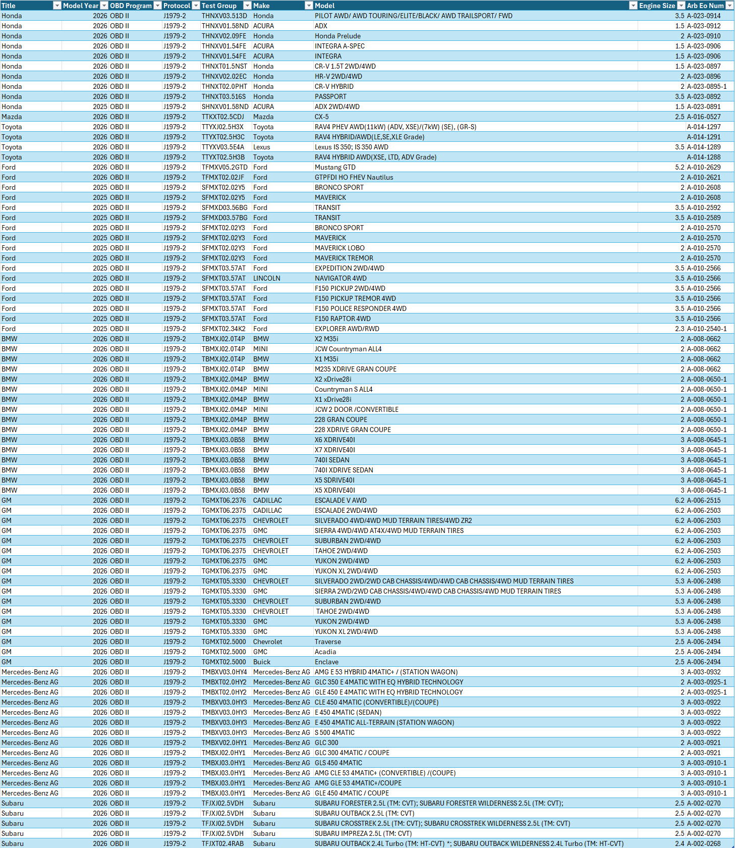
What Vehicles are Currently Certified and Equipped with Unified Diagnostic Services? (January 21, 2026)
Introduction to Evaporatvie Emissions
Evaporative emission systems (EVAP) have been used as an anti-pollution system on most 1970 light-duty vehicles sold in California. Some medium/heavy-duty and 4x4 vehicles had later deadlines. Starting in 1971, all Federal/USEPA vehicles (forty-nine states) were required to be equipped with some evaporative emission system. EVAP regulations prohibited uncontrolled hydrocarbons from entering the atmosphere from the evaporative emission system.
Evaporative emission systems trap, store, and release gasoline vapors into the engine to mix with the incoming air/fuel mixture. These gasoline vapors are also called volatile organic compounds (VOCs). Volatile organic compounds are those parts of a fuel’s composition that contribute to photochemical smog when introduced into the atmosphere.
Over 20% of the hydrocarbons a motor vehicle generates result from fuel evaporation when the engine is not running. Hydrocarbon emissions caused by evaporative emissions can be defined as follows:
1. Diurnal Loss: Vapors vent to the charcoal canister as the ambient temperature rises during the day. Excess vapors will enter the atmosphere if the charcoal canister reaches a saturation point. Diurnal loss is measured with the engine off and usually occurs within 35 minutes of shutdown.
2. Hot Soak: The engine remains hot long after the vehicle has been turned off. For 35 minutes, emissions are measured to gauge this event. Evaporation occurs from fuel that has been heated in the engine compartment and all fuel supply and vent lines.
3. Resting Loss: Gasoline permeates rubber and plastic components in the fuel system while the vehicle is at rest. This event occurs when the vehicle has been turned off and allowed to sit for at least thirty-five minutes in a steady or decreasing ambient temperature condition.
4. Running Loss: Gasoline vaporizes as the engine is running. The running loss test is conducted in an enclosure on a dynamometer. The exhaust gases are routed out of the enclosure, leaving only vapors from evaporation. The running loss test occurs over one hour while the vehicle is driven through three consecutive Federal Test Procedure (FTP) drive cycles.
The EPA has devised the Sealed Housing Evaporative Determination Test (SHED). All evaporative hydrocarbon emissions from fuel, tires, and plastics are collected and measured during this test. This test includes a multi-day Diurnal Test (Enhanced Evaporative Emission Test), where the vehicle is repeatedly heated and cooled to simulate the effects of hot and cold ambient temperatures. The figure below shows a drawing of the SHED setup. Courtesy of Colorado State University-NCVECS
Factory emission tests have determined that an EVAP system with a leak as small as .020 inch can yield an average of 1.35 grams of hydrocarbons per vehicle per driven mile. This is over thirty times the current allowable exhaust emissions standard. Evaporative System Operation The Evaporative Emission Control (EVAP) system is designed to store and dispose of fuel vapors usually created in the fuel system, preventing its escape to the atmosphere. The EVAP system delivers these vapors to the intake manifold to be burned with the usual air/fuel mixture. This fuel charge is added during periods of closed-loop operation when the closed-loop fuel control system can manage the additional enrichment. Improper operation of the EVAP system may cause rich driveability problems and failure of the Two-Speed-Idle test or Enhanced I/M loaded mode ASM test. The EVAP system is a fully closed system designed to maintain stable fuel tank pressure without allowing fuel vapors to escape into the atmosphere. Fuel vapor is usually created in the fuel tank due to evaporation. It is then transferred to the EVAP system charcoal canister when tank vapor pressures become excessive. The canister absorbs fuel vapors until it becomes fully saturated. When engine operating conditions can tolerate additional enrichment, these stored fuel vapors are purged into the intake manifold and added to the incoming air/fuel mixture.
Types of Evaporative Emission Systems
Identifying the type of EVAP system equipped on the vehicle is essential. Since 1970, several methods have been used. The following are the most common:
1. Non-ECM-controlled EVAP systems use solely mechanical means to collect and purge stored fuel vapors. Typically, these systems use a ported vacuum purge port and a Thermo or Ported Vacuum Switch to prohibit system operation during a cold start or warm-up.
2. Pre-OBD II ECM Controlled EVAP systems use a ported or intake manifold vacuum purge source with a duty-cycled vacuum switching solenoid. This type of EVAP system can provide more precise control of purge-flow volume and operation inhibition. It cannot check the system for leaks. Sometimes, the ECM does not know if purge flow occurred.
3. OBD II systems will be seen in either Non-Enhanced or Enhanced form. This book will address these two systems:
A) Non-enhanced systems can only detect purge flow but cannot check the system for leaks. These systems do not include a readiness monitor. They were installed on some 1996 and 1997 model-year vehicles.
B) Enhanced systems can detect purge flow and system leaks by using vacuum switches or pressure sensors. A vent solenoid, vent valve, or closed canister valve can identify them. Some systems test when the key is turned off. All systems include a readiness monitor. Enhanced EVAP has required equipment on all 1998 and newer model-year vehicles. Enhanced EVAP systems can be divided into various types that accomplish the same goal using different methods. Depending on the model year, enhanced evaporative emission systems must be capable of identifying leaks as small as .040 inch or .020 inch. These systems perform the test by either lowering the pressure, thus creating a vacuum, or increasing the pressure through a pump.
Methods of Testing Enhanced Evaporative Emission Systems
1. Vacuum Decay: The vacuum method utilizes a purge solenoid, vent solenoid, or close canister valve (CCV) and a fuel tank pressure sensor (FTP). These components monitor the evaporative emission system for leaks. This system uses an engine vacuum through the purge solenoid to create a vacuum in the closed system. This is the most common system in use today.
2. Fuel Tank Pressure/Canister Vacuum: This system has been used by Honda and Toyota and can isolate the fuel tank from the charcoal canister to pinpoint the leak. Toyota utilizes two versions of this system: a non-intrusive system, which was used from 1996-2002, the second is called an intrusive system, which was introduced in 2000.
3. Leak Detection Pump: This system pressurizes or creates a vacuum in the evaporative emission system through a leak detection pump (LDP). LDP has been used by Audi, BMW, Chrysler, Hyundai, Mitsubishi (Chrysler products), Volkswagen, and Volvo. In 2000, BMW, Hyundai, and Mazda introduced a Diagnostic Module for Tank Leakage (DM-TL) pump to pressurize the system with the engine off. Toyota 2005 introduced a vacuum pump module key-off system.
4. Engine off Natural Vacuum Leak: This system works on the fluid’s vacuum/pressure principle in a closed container. As temperature increases - the pressure increases if no leaks are present. This system primarily tests for a very small leak (.020”). It first appeared in 2002 model year vehicles, and Chrysler, Ford, GM, and Honda use variations of this system. To inspect or repair these systems, the technician must be able to identify them.
EVAP Systems

Onboard refueling vapor recovery system (ORVR)
Even though the EVAP system performed well, it could not control the hydrocarbons escaping during refueling. Starting in 1998, vehicles were required to have an On-board Re-fueling and Vapor Recovery (ORVR). The vapor return systems installed on gas pump nozzles had relatively little effect on the amount of vapor escaping.
As a result, the ORVR system was created to trap the hydrocarbons released during refueling. An ORVR system was designed to control vapors produced during refueling by routing them to the canister during fuel refill.
As fuel is channeled into the Fuel Tank, the ORVR system directs the fuel vapor to be stored in the EVAP Canister. This vapor is later routed to the engine to be burned during normal combustion. The EVAP and ORVR systems have been very successful in the containment of hydrocarbon emissions.
To see how this is accomplished, let’s first take a look at the components in the system: The ORVR system can consist of the following:
1. Fuel Filler Neck: The filler neck on many models consists of the main pipe for the fuel delivery into the tank, the one or smaller lines that help control fuel vapor flow, and tank overflow control. The ORVR fuel filler neck is designed to make a dynamic liquid seal, dispensing fuel from the fuel nozzle. The smaller diameter filler neck creates suction around the fill neck opening. It draws air and any escaping vapors into the filler neck to be pushed into the tank during refueling.
2. Fuel Shut-Off (Fuel Cut) Valve: The fuel cut valve (anti-spit back) valve prevents fuel from splashing back up the filler neck. The spring-loaded valve opens automatically when refueling. The force of the fuel flowing is enough to open the valve when refueling.
3. Fill Vent Valve: The fill vent valve controls the flow of vapors during refueling. The valve is open when the tank is near empty. As fuel enters the tank, the vapors flow into the charcoal canister through the fill vent valve. A float in the valve rises as the fuel level approaches the full point. When the tank is full, the valve is closed to prevent liquid fuel from going through the valve.
4. Fuel Rollover Valve: The primary purpose of the rollover valve is to allow vapors to flow from the fuel tank to the charcoal canister. When the vehicle is parked on a steep incline, the valve is closed to prevent fuel spillage from the fuel tank into the charcoal canister. In the event of a vehicle rollover, it keeps liquid fuel out of the EVAP canister.
5. Fuel Liquid/Vapor Separator: The liquid-vapor separator prevents liquid fuel droplets from reaching the vapor canister. A barrier inside the separator allows vapor to travel freely, but fuel droplets are too heavy and trapped. The droplets either travel back into the fuel tank or vaporize and are stored in the charcoal canister.
6. Two-Way Valve for Pressure/Vacuum Relief: The two-way valve is a directional valve that allows fresh air into the charcoal canister. The valve also acts as a pressure relief valve if the system pressure gets too high. The arrow on the valve points toward the charcoal canister. When testing this valve, air should pass easily in one direction, and airflow should be somewhat restricted in the other direction. When replacing this valve, refer to the system diagram for the correct installation. The arrow on the valve indicates the direction of airflow. This valve must be installed in the right direction.
7. Hoses, Pipes, and Gaskets: The hoses, pipes, and clamping devices are critical to proper ORVR operation. Misrouted, damaged, or disconnected hoses can cause various symptoms, including difficulty filling the fuel tank with fuel or the MIL light coming “ON” for an evaporative system leak Diagnostic Trouble Code (DTC).
8. Charcoal Canister: The charcoal canister stores fuel vapors. The canister contains activated charcoal. During refueling, the charcoal can absorb fuel vapors, cleaning the vapor mixture and allowing uncontaminated air to escape into the atmosphere. Fresh air drawn into the canister during purging releases the fuel vapors and recharges the charcoal. Details of this are covered in the evaporative system components section.
These components work together with the ECM to prevent fuel vapor from escaping and route it to the intake manifold to be burned during normal combustion. Either through heat or agitation, fuel vapor builds up inside the Fuel Tank.
The fill pipe diameter reduces after the unleaded restrictor plate. This restricted pipe size forms a liquid seal into the tank rather than letting fumes escape. The check valve is spring-loaded to prevent fuel from entering the filler pipe. During refueling, a small amount of air is drawn into the filler pipe to prevent fuel vapors from escaping into the air during refueling. These vapors are drawn into the fuel nozzle and returned to the station’s tank.
The vapor valve vents to the canister through the ORVR valve, which has a float to close off the vent when the tank is full. A faulty ORVR valve can leak or cause difficulty when filling the tank, as pressure builds and causes early shut off of the filler nozzle. Both valves shut off during a rollover event.
The ORVR valve may have a pressure relief valve, spring loaded in both directions for zero pressure in the tank and zero vacuum, that is vented to the atmosphere. A buzzing noise may be heard in hot weather conditions just as the engine is turned off. This is because the tank is being sealed under low pressure.
The primary purpose of this system is to route the fuel vapors that may escape from the filler neck during vehicle refueling into the EVAP canister. The canister absorbs these vapors and then purges them during driving.
Operation As the tank is refueled, a slight vacuum is created in the Signal Line by moving fuel at the top of the filler neck. This vacuum signal is applied to the top of the Refueling Control Valve by the Signal Line, which opens the Refueling Control Valve. The fuel entering the fuel tank creates a slight positive pressure in the tank, which causes the EVAP Vapor Cut Valve to open. With the Refueling Control Valve and EVAP Vapor Cut Valve open, fuel vapor can travel directly from the tank to the EVAP canister via the Refueling EVAP Vapor Line. The Recirculation Line minimizes the amount of fresh air pulled into the tank by recirculating the air in the tank, to the filler neck, and back to the tank.
Troubleshooting Most concerns about the ORVR system will be "slow-fill" concerns. A faulty ORVR valve can leak or cause difficulty when filling the tank, as pressure builds and causes early shut off of the filler nozzle. Some owners may experience difficulty 'filling their vehicles with gasoline and a premature shut-off condition due to the gas pump nozzles installed at their gas stations. The nozzles at these stations are in the process of being retrofitted or replaced by the nozzle manufacturers. In the meantime, owners should follow instructions posted near the gas pump and try filling the vehicle at a different gas station. If the refueling difficulty continues, verify that the 1/2" vapor path from the fill vent valve on the gas tank to the air filter on the charcoal canister is entirely free and clear. To perform the procedure below, ensure the fuel tank is below 1/4 tank full. To quickly determine the general location of a possible vapor path restriction, Disconnect the hose connected to the canister side of the liquid-vapor separator. Take the vehicle to a known "good" or major brand gas station. A. If the vehicle accepts fuel, the restriction is between the liquid-vapor separator and the air filter. B. The restriction is located between the liquid-vapor separator and the fuel tank if the vehicle does not readily accept fuel. After the restriction has been isolated to either half of the system, inspect each component to ensure it is free and clear of any restrictions. Verify that no back pressure can be felt anywhere between the fill vent valve and the air filter at the canister. All hoses and tubes for the ORVR System must be free and clear for proper operation. The ORVR lines are part of the EVAP system, so don't overlook them when diagnosing an EVAP leak concern. Blow through one end of the pipe using lung power when checking the liquid-vapor separator. NO back pressure should be felt. Please verify that the Fill Vent Valve is open by carefully removing the valve and confirming that the white plastic shut-off plunger moves freely inside its cage. A hard-to-fill condition may result if the Fuel Cut Valve plunger is stuck closed. Verify that the plunger moves up and down freely, allowing fuel to enter the tank but does not allow fuel to travel up the neck (under pressure). The plunger should be "up" (closed) in its free state. When working with the Fill Vent Valve and associated plumbing, replace the hoses with the proper hose clips to prevent fuel from getting trapped/puddled in the vapor hose. Return fuel from the liquid-vapor separator must have a clear path to drain back to the tank. Related DTCs: P0442 Small Leak P0456 Very Small Leak
EVAP Components

EVAP Testing

"NEW" Smog Check News
This page will address changes to the State of California Smog Check Program.
Future Testing of Pre-OBD II Vehicles
• BAR’s Sunset Bill (AB 1263) includes several provisions including:
• Authorizes BAR to establish a centralized testing network for model year 1995 (pre-OBD II) and older vehicles no earlier than January 1, 2025
• Must be competitively bid • May include subcontracted licensed Smog Check stations (i.e., centralized/hybrid)
• Authorizes BAR to begin testing model year 1996 -1999 vehicles using the BAR Onboard Diagnostic Inspection System (BAR-OIS) no earlier than January 1, 2025
Considerations
• Although the population of older vehicles (model year 1976 -1995) is relatively small (615,200), it is still a large part of the Smog Check emissions inventory (17.6%)
• Continued testing of this population of vehicles is critical to meeting State Implementation Plan (SIP) commitments
• Shifting the testing of model year 1996 -1999 to the BAR-OIS without establishing an alternative testing network would:
• Provide even less incentive for STAR stations to maintain BAR-97 equipment
• Exacerbate challenges for owners of older vehicles seeking BAR-97 inspections
• Increase pressure to exempt this population of vehicles from Smog Check
• Establishing a centralized/hybrid network and shifting the testing of model year 1996 -1999 vehicles benefits consumers and the Smog Check industry
• Improved air quality
• Reduced BAR-97 testing costs for consumers who own older vehicles
• Helps to ensure adequate program area coverage for BAR-97 testing
• Removes burdensome BAR-97 equipment requirements for STAR stations who no longer wish to continue BAR-97 testing
• Increases the population of vehicles that can be tested on the OIS
• Allows a pathway for existing high-performing stations to continue BAR-97 testing
Metrics / Criteria
• The cost of a BAR-97 inspection
• The cost of performing a centralized/hybrid BAR-97 inspection
• Smog Check station willingness/ability to maintain BAR-97 equipment
• BAR-97 vendors' willingness/ability to maintain BAR-97 equipment
• BAR-97 test volume of STAR and non-STAR stations • Population of older vehicles
• Contribution of older vehicles to the emissions inventory
• Consumer complaints relative to the ability to obtain a BAR-97 inspection
Contact Information
Clayton Leek
clayton.leek@dca.ca.gov
Register for a Smog Update Class
- Apply (opencccapply.net)
- When completing the application, you will be asked about your Educational Goals. Check non-degree and maintain a Certificate or License (Upgrading your Skills). Selecting any other options will refer you to a counselor, holding up your registration.
- Please add a cell phone and regular email address to your account.
- Usually, but not always, within 24 hours, they will send you an email allowing you to register.
- Once in WEBSMART, select Student Services, Registration Add/Drop, Spring 2025 Semester.
- Online Spring 2026 Smog Check Update Classes (2025 Smog Check Update):
- February 7/8, the class Course Reference Number (CRN) is 48647
- May 2/3, the class Course Reference Number (CRN) is 48648
- After processing the application, you will be required to create a WebSmart login. Please change your educational goal in WebSmart to “Improve job skills or self-development” to exempt you from orientation, assessment, and counseling.
- Pay your fees.
- I will send you specific information about the course and its materials before the class begins.
If you have any questions, email me at escalambre@smccd.edu.
Industry Conferences
ASE Alliance Foundation Conference
July 20-23, 2026 Embassy Suites - Frisco (Dallas), TX
Rick Escalambre will present two workshops: they will be announced at a later date.
For more information, click on
https://www.aseeducationfoundation.org/
Webinars
ASE offers free weekly Tuesday Webinars at 4 PM EST/1 PM PST, covering a variety of topics. They offer two options for viewing the webinars: you can watch them live or view the recorded sessions at your convenience. Within one to two days after the initial online presentation, ASE will email you a link to the recording.
For more information, click on
https://www.ase.com/webinar-subscribe
WorldPAC offer free online Lunch and Learn Webinars:
WORLDPAC Training Institute (WTI) - Technical Lunchtime Training
Automotive Training Seminars offed paid Webinars conducted by some of the best trainers in the country:
Home | Automotive Seminars, Inc.
Future Online Training
- Training would be offered as a single session or multiple sessions.
- Each session could last 1 to 3 hours.
- A variety of topics could be offered: Ignition and Fuel System Essentials, Computer Controls, Global OBDII on UDS, Handling Incomplete Readiness Flags, and Running Monitor Tests.
- A PDF file for the topic will be provided, including student notes and, where applicable, links.
- Group size would be limited, and microphones and cameras would be enabled to facilitate two-way dialogue. This will allow for a personalized learning environment.
- Each session would be recorded for future review.
- There would be a fee for the online training.
- A Certificate of Completion will be awarded.
Industry Resources
Articles by Rick
YouTube Videos
Videos created by Rick can be viewed at Rick Escalambre - YouTube
The videos were created during actual class sessions in the classroom or the lab.
***Contact Rick***
If you want an email notification when significant additions are made to this website, let me know, and you will be notified. If you find errors or have any questions, please email me.
