OBDII COMMUNICATIONS
This section will cover the following topics:
- OBD II Communication Protocols
- Testing at the Diagnostic Link Connector (DLC)
- Scan Tool Usage
1. OBD II Communication Protocols
One OBD II requirement is that the vehicle contains a standard serial data communications link to a scan tool. Communication protocols use changing voltage signals to communicate with the scan tool and other modules. The difference between communications protocols is the digital voltage signals generated by the ECM.
At this time, there are five communications protocols used on OBD II systems, two defined by the Society of Automotive Engineers (SAE) and three defined by the International Standards Organization (ISO):
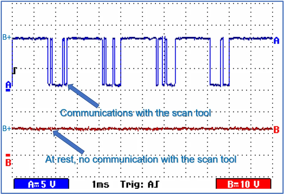
- SAE J1850 10.4K Variable Pulse Width (VPW): used by GM and referred to as a Class 2 data line; it utilizes a single-wire 7-volt bus that communicates to the scan tool through DLC pin 2.
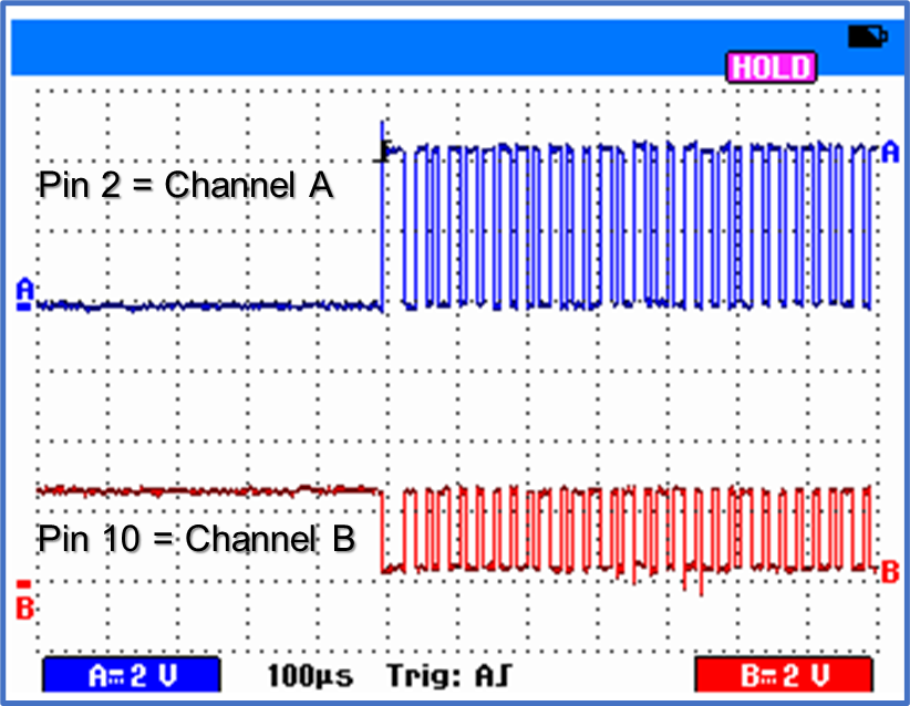
- SAE J1850 41.6kbps Pulse Width Modulation (PWM): It is used by Ford and utilizes a two-wire 5-volt bus that communicates to the scan tool through DLC pins 2 & 10.
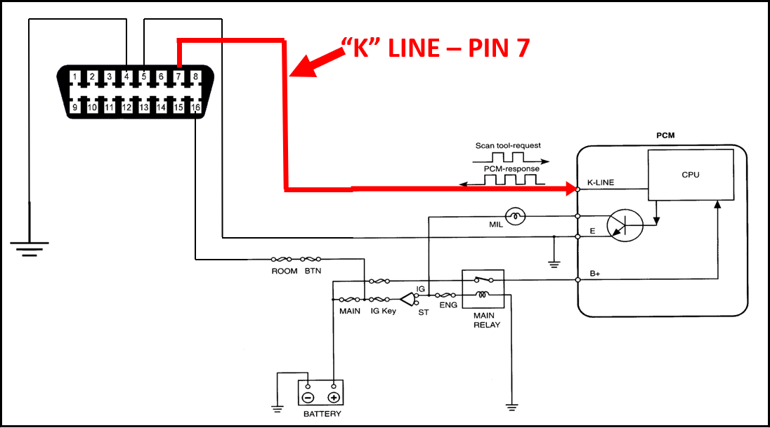
- ISO 9141-1: 10.4kbps: It is used by Asian and European manufacturers and utilizes a single-wire 12-volt bus that communicates to the scan tool through DLC pin 7.
- ISO 14230 Keyword (ISO 9141-2): a newer version of ISO 9141 that looks the same. A European protocol that communicates to the scan tool through DLC pin 7.
- ISO 15765 500kbps Controller Area Network (CAN): It is also called CAN "C" and was phased in during the 2005-2007 model years. It became the standardized powertrain communications protocol for all 2008 and newer vehicles. CAN-equipped vehicles communicate to the scan tool through DLC pins 6 & 14.
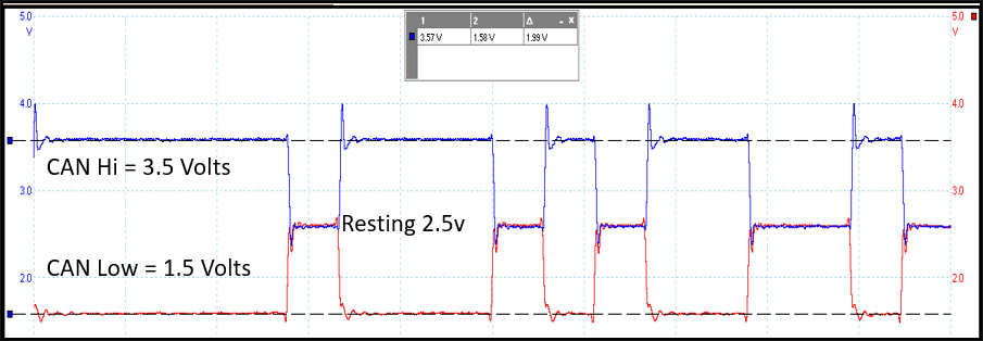
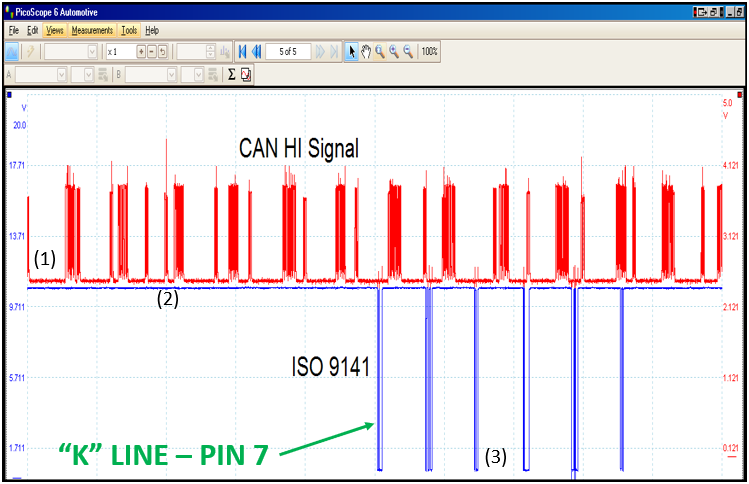
The scope pattern below was captured from a 2005 INFINITI. The CAN "C" Hi signal transmits data from modules other than the powertrain modules through pins 6 & 14. The ISO 9141 "K" line communicates serial data from the ECM to the scan tool through DLC pin 7.
Note: Because of the three-year phase-in, both CAN "C" and ISO 9141 protocols can be on the same vehicle. High-Speed CAN "C" was required to transmit data through DLC pins 6 & 14, while ISO 9141 transmitted data on the "K" line through pin 7.
2. A Diagnostic Link Connector (DLC) was added to the vehicle to connect modules to the scan tool. It must be under the dash between the driver's door and the center console. Unfortunately, not all manufacturers comply with this requirement, so sometimes they will be outside this area.
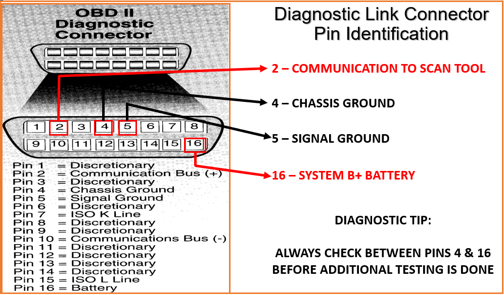
OBD II requires that four pins be standardized on all 1996 and newer vehicles:
- Pin 16 is a fused Battery Voltage that provides power to the scan tool.
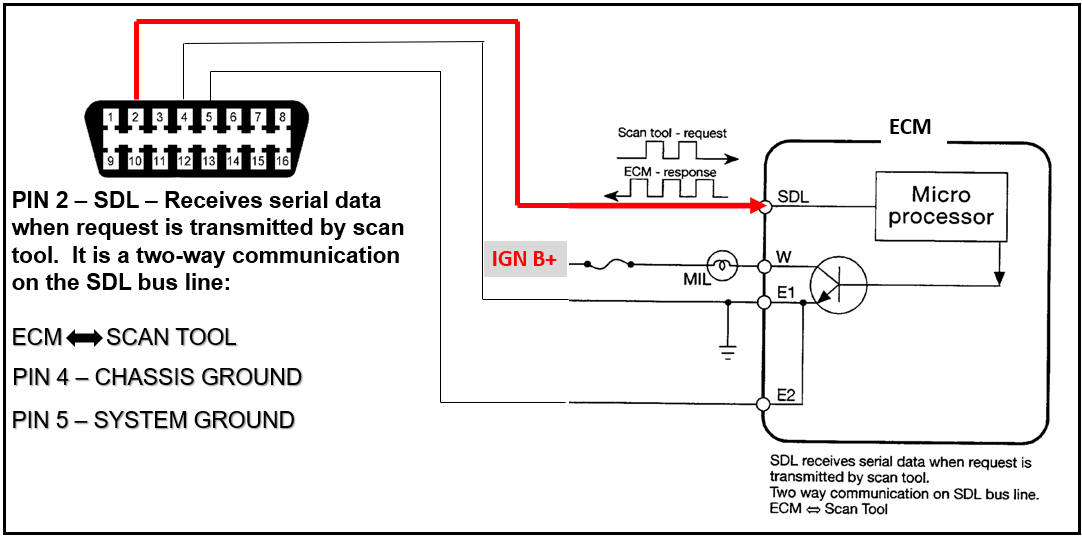
- Pin 4 is the Chassis Ground for the Powertrain Control Module (PCM) and scan tool.
- Pin 5 is the Signal Ground for the Powertrain Control Module (PCM).
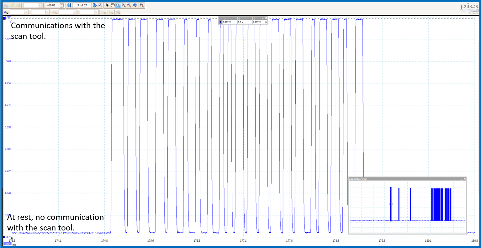
- Pin 2 is the SAE J1850 OBD II terminal. In Global OBD II, scan tool data is supposed to be transmitted on this line. This will not be the case, depending on the communications protocol used.
Pin 2 represents Global OBD II communications called SAE J1850. It is a bi-directional line, so the scan tool can send a request to the PCM and receive responses from the PCM.
Pin 7 represents the ISO 9141 or 14230 communications line. It is a bi-directional line, so the scan tool can send a request to the ECM and receive responses from the ECM.
Testing At the DLC
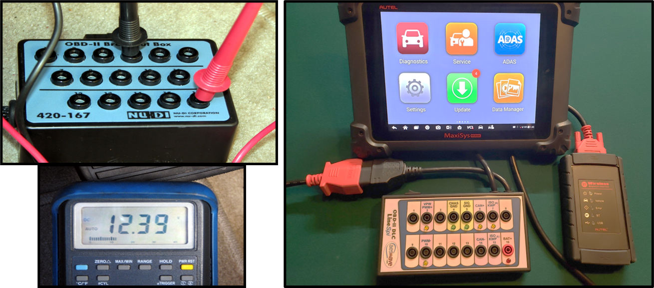
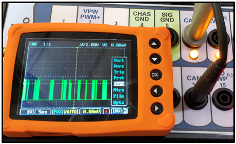
The picture below shows how LIneSpi box fits into the circuit. Communications pins 2, 6, 7, and 10 have a LED. When the data line is communicating the Led should be flashing. A LED remaining on or off all the time is an indication that no communications is taking place.
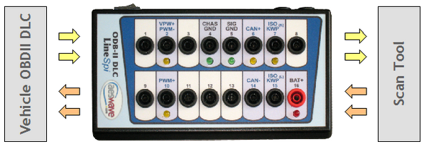
The picture below shows serial data communications occurring on the CAN "C" bus. When CAN "C" is talking the LED should be illuminated. In this case, the LED is illuminated, and a waveform is present.