DRIVE CYCLE OVERVIEW
The Drive Cycle information presented in this section is from real-world research. The research data was collected while driving hundreds of vehicles on a dynamometer or the road. Many but not all types of makes and models were tested. Video recordings and scan tool snapshots were used to capture the necessary data.
This section about OBD II Drive Cycles will cover the following:
- Drive Cycles Overview
- Developing a Drive Cycle Plan
- Scan Tool Pre-Checks
- Preparing to Drive a Drive Cycle
- Variables for Driving the Drive Cycle
The purpose of a drive cycle is to allow the ECM to run various individual monitor tests and pass judgment for all readiness flags in one trip. When the ECM completes monitor tests for each non-continuous readiness flag, their status will flip to complete. The non-continuous readiness flags include:
- Air Fuel Ratio (AFRS) or Oxygen Sensor (O2) Heaters
- Air Fuel Ratio or Oxygen Sensors
- Catalytic Converter (CAT)
- Exhaust Gas Recirculation (EGR)
- Evaporative Emissions (EVAP)
- Secondary Air (AIR)
A trip begins with a key-on event, idling the vehicle, putting it under light to moderate acceleration, driving at steady throttle, under deceleration, and then a key-off event. In some cases, the key-off event will trigger running the required monitor test to flip an O2 Heater and EVAP readiness flag to complete.
EPA uses different drive cycles to certify new model vehicles. More information about the drive schedules can be found at EPA Drive Schedules. The assumption is that daily driving by the consumer will allow for the completion readiness flags. This might take multiple trips over days, weeks, months, or years. Before the Controller Area Network (CAN) implementation, the frequency at which each monitor test runs was not tracked. For CAN "C" vehicles, CARB/EPA now tracks how frequently monitor tests run long enough to detect a failing system. Any manufacturer failing to meet the required minimum ratio could be required to issue a recall. In-Use Performance Monitor Tracking will be covered in MODE $09.
The drive cycles used by the technician to complete readiness flags differ from the EPA Drive Schedules. The driving patterns shown in the Drive Cycle Patterns section are shorter distances, less aggressive, and should take less time than the drive EPA Drive Schedules. Drive cycles differ between each manufacturer and sometimes within the same manufacturer.
When a drive cycle is performed on a dynamometer, setting the readiness flags to complete can be more manageable. Unfortunately, shops that do not have a dynamometer will have to drive on the road. Completing an entire drive cycle can be delayed because of the types of roads in the area, the distance from a freeway, or the number of vehicles on the road. Vehicles equipped with a full-time four-wheel drive cannot be driven on a two-wheel drive dynamometer; they must be road tested. Four-wheel drive dynamometers are available, but very few shops have one.
A technician attempting a drive cycle on the road faces variables so that readiness flags might be completed out of the expected order. Let's say the EGR system was repaired and cleaned, and the technician wants to verify the effectiveness of the repair by taking it for a test drive. Does the technician have to perform a complete drive cycle? Can the technician perform the part of the drive cycle that satisfies the EGR monitor tests required to set the readiness flag to complete? The answer is simple: drive the part of the drive cycle the ECM needs to pass judgment on the EGR system. The irony is that while verifying the repair of the EGR, the technician may unknowingly run and complete other readiness flags. Published Drive Cycle patterns, like the ones included on the website, are for ideal conditions.
DEVELOPING A DRIVE CYCLE PLAN
Developing a Drive Cycle Plan
At this point, it is time to identify a plan for driving the Drive Cycle. The method is referred to as the Enable Criteria/Conditions. This plan can be found in the following:
- The OBDII Drive Cycles tab of this website.
- Mitchell Pro-Demand, ALLDATA, IDENTIFIX, YouTube, or Google.
- OEM websites if you have a paid subscription.
- The Freeze Frame Data should have been captured before clearing the memory.
- In the Generic Drive Cycle Criteria part of this section.
The following capture shows an engineering data sheet each manufacturer must submit to CARB. It indicates the name of the monitor test, the DTC, enable criteria, and how many times the test will run per trip if the system fails. Note: The most relevant information is shown, but a couple of columns were deleted from this chart for a better fit on this page.
The fourth column shows the enable criteria for running this monitor test. The fifth column means the test can only run "Once Per Trip." When a DTC is referred to as "Once Per Trip, " the test must run to completion for the readiness flag to Complete, pass or fail.
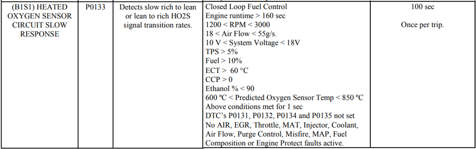
The capture below the fifth column says, "Frequency: 2 times per key cycle". If the monitor test result indicates a failing test, the ECM will run the monitor test a second time in the same key cycle. The P0135 monitor test requires the O2 Heater readiness flag to flip to Complete, pass, or fail.
There are essential variables to driving a Drive Cycle that factory manuals, service information systems, and the internet do not tell technicians. The following information was developed through many trials and errors.
GENERIC DRIVE CYCLE CRITERIA more to be added!
SCAN TOOL PRE-CHECKS
When preparing to drive a drive cycle, there are essential checks before starting the vehicle. These checks are best made using a global scan tool. Do these checks with the key-on engine-off (KOEO). The issue with doing these checks with the key-on engine-off is that it could void a cold start timer or condition. This could affect the running of monitor tests for EVAP, O2 Heater, and Secondary Air.
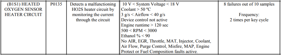
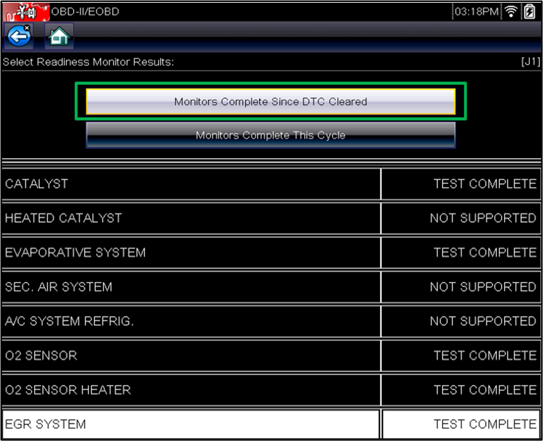
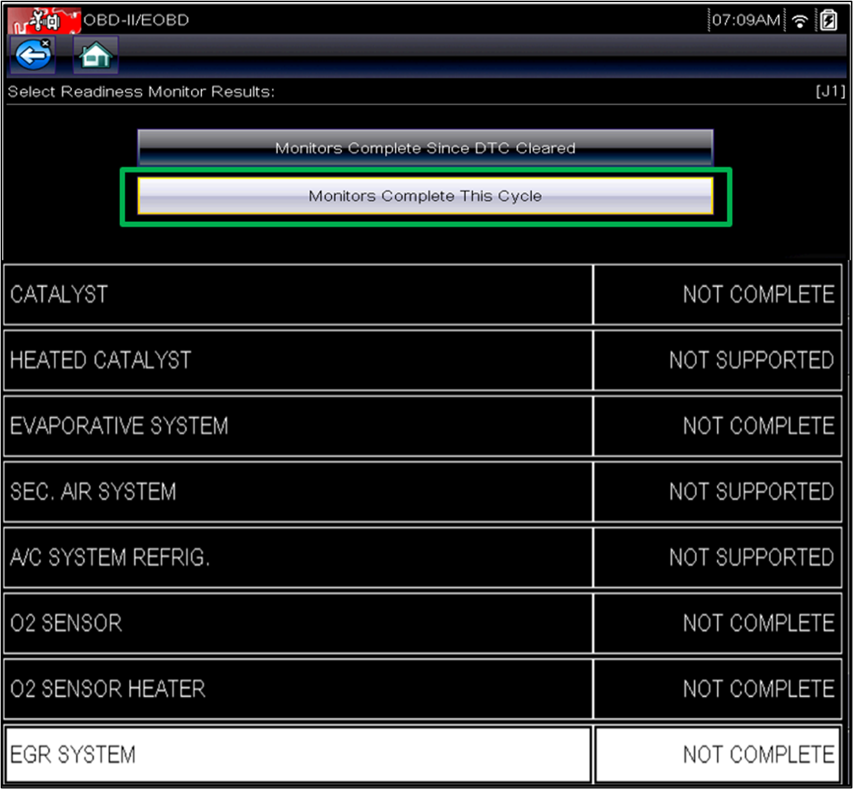
Begin by checking the readiness flag status for Monitors Complete Since DTC Cleared. This page shows if each readiness flag has been completed a minimum of one time since the last time the memory was cleared and the readiness flags were reset. It did not identify when a readiness flag was last completed. This page is part of a state emissions inspection's pass/fail criteria.
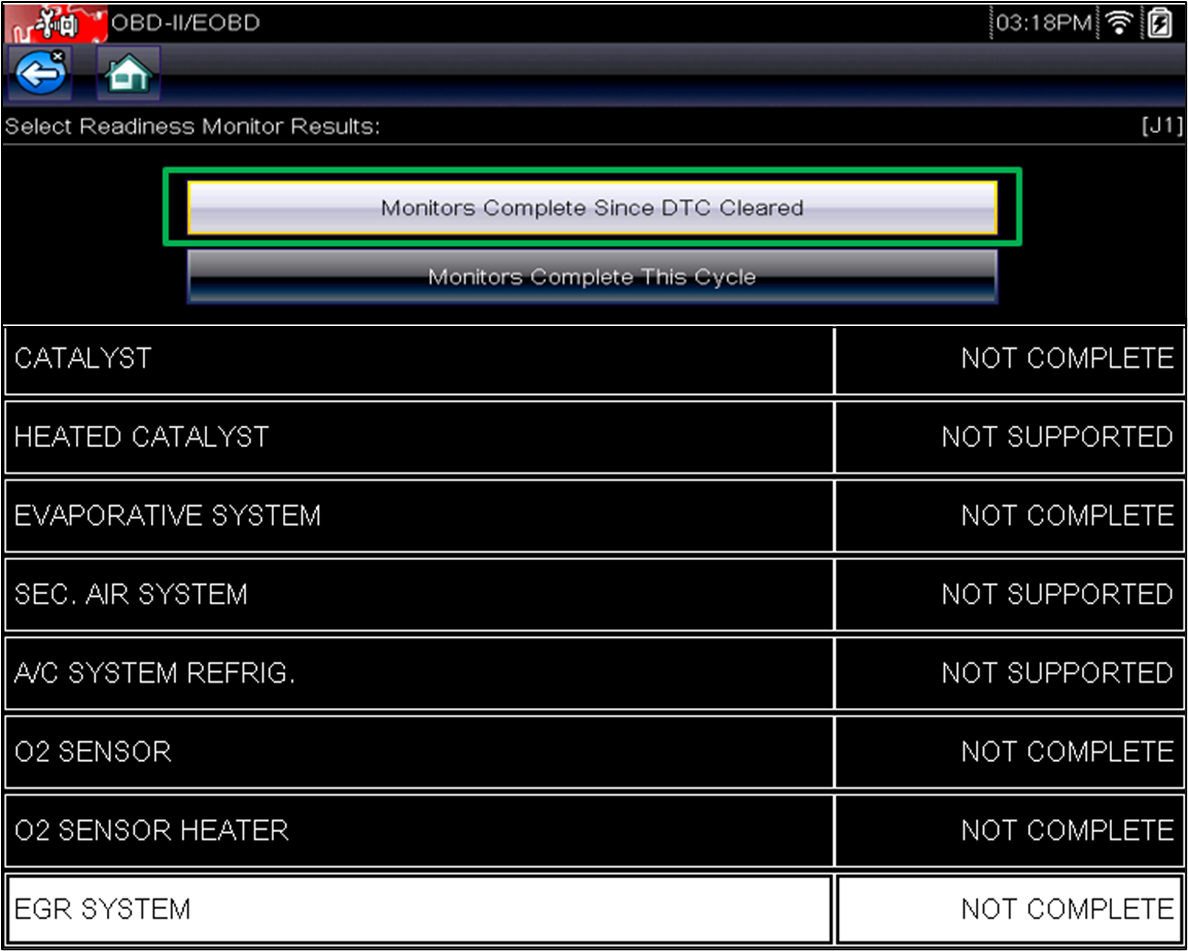
The capture below shows that none of the readiness flags have been completed. The most likely causes for these results are the ECM's memory cleared with a scan tool, the keep alive memory was removed because the battery went dead, power was removed from the ECM, or the ECM was reprogrammed.
Before the implementation of CAN, readiness status was only reported for Monitors Complete Since the DTC Cleared. The problem was that the readiness flag status did not reset. The only way to know if the monitor test ran and flipped the flag was to clear the memory and drive the vehicle.
Another page was added for CAN-equipped vehicles, identifying Monitors Complete This Cycle. This is also referred to as PID $41. The readiness flags are reset to Not Complete at each key-on cycle, as shown below. This page allows the technician to drive the vehicle and watch the readiness flag status without clearing the memory. If the monitor tests run and pass, the flag status will be updated immediately to Complete. This page is not part of a state emissions inspection's pass/fail criteria.
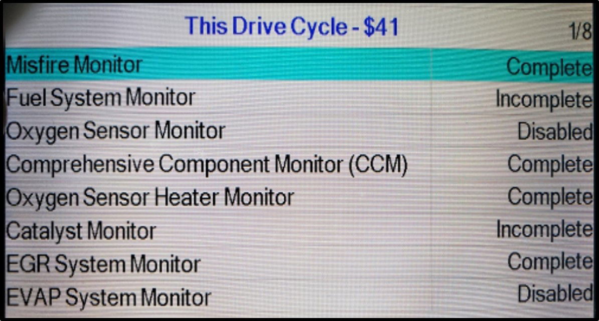
Readiness Flags Monitor Status This Drive Cycle (PID $41)
Another helpful precheck, if the scan tool supports it, is PID $41 Monitor Status This Driving Cycle. If supported, it can be located under readiness flag status in the PID data list or MODE $06 for the specific monitor test. There are cases where some scan tools do not display PID $41. The picture below is of an INNOVA 7111 scan tool. This case shows that the Oxygen Sensor and EVAP system monitor tests are suspended for this key cycle.
When the key is turned on and the engine is started, the ECM uses criteria established by the California Air Resources Board (CARB) to determine if the status monitor test for a non-continuous readiness flag is enabled or disabled for the current driving cycle. CARB criteria are not the same as OEM enable criteria.
The enable criteria established by CARB that will display the monitor as disabled include:
- Engine-off soak not long enough (e.g., cold start temperature conditions not satisfied).
- Monitor the maximum time limit, or the number of attempts/aborts exceeded.
- Ambient air temperature is too low or too high.
- BARO pressure is too low (altitude equals or exceeds 8000ft).
- A conflicting Diagnostic Trouble Code (DTC) is present.
The monitor will not indicate "disabled" for operator-controlled conditions such as rpm, load, and throttle position. It will also not show "disabled" from key-on because the minimum time limit has not been exceeded or engine warm-up conditions have not been met since these conditions will eventually be completed as the vehicle continues to be driven.
If the vehicle is driven to a different altitude or ambient air temperature conditions on the same trip, the monitor status may change from enabled to disabled. The monitor status will not change from disabled to enabled if the conditions change back. This could result in a monitor test showing disabled but eventually showing Complete.
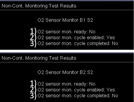
The next two captures display PID 41 results for O2 Sensors B1 & B2.
- Monitors Complete Since the DTC Cleared - ready: No
- Monitor Status This Driving Cycle - enabled: Yes
- Monitors Complete This Cycle - completed: No
These Test Results indicate that monitor tests should be able to run this trip if the OEM enable criteria are met.
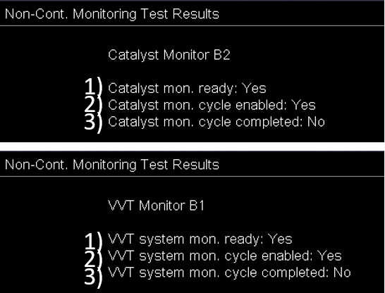
The next two captures display PID 41 results for Catalyst B2 & VVT B1.
- Monitors Complete Since the DTC Cleared - ready: Yes
- Monitor Status This Driving Cycle - enabled: Yes
- Monitors Complete This Cycle - completed: No
These Test Results indicate that monitor tests should be able to run this trip if the OEM enable criteria are met. If they run to completion, the Monitors Complete This Cycle should update to Complete when testing is done.
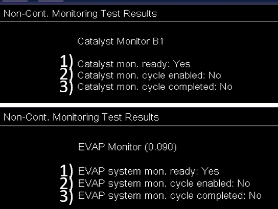
The next two captures display PID 41 results for the Catalyst B1 & EVAP (0.090").
- Monitors Complete Since the DTC Cleared - ready: Yes
- Monitor Status This Driving Cycle - enabled: No
- Monitors Complete This Cycle - completed: No
These Test Results indicate that monitor tests are disabled during this driving cycle because some parts of the CARB enable criteria cannot be met.
In summary, PID 41 Monitor Status This Drive Cycle indicates that a blocking condition will prevent a readiness flag monitor test from running to completion during the current ignition cycle.
PREPARING TO DRIVE A DRIVE CYCLE
There are essential variables to driving a Drive Cycle that factory manuals, service information systems, and the internet do not tell technicians. The following information was developed through trial and error.
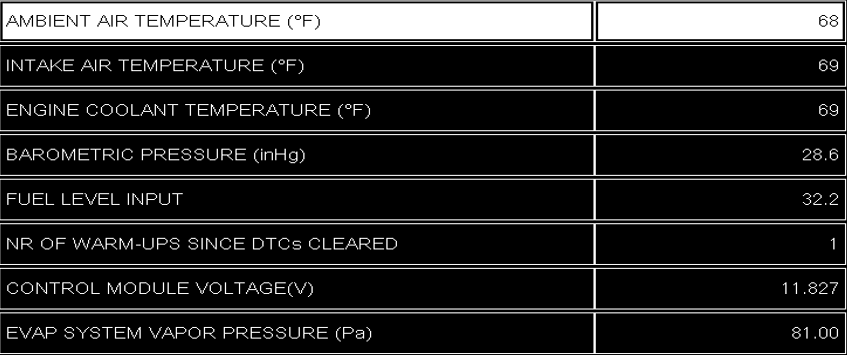
Some fundamental procedures should be implemented as part of the preparation to drive the drive cycle. Before starting the vehicle, select a small group of global PIDs that could impact the running of a single or multiple monitor test. These PIDS are called blockers because they can prevent monitor tests from running. Knowing their “normal” values and seeing what they are before starting the vehicle can provide an excellent starting point, possibly saving the technician time and the customer money. These PIDs should be selected:
- Temperature Sensors: Compare ambient air, intake air temperature (IAT), and engine coolant temperature (ECT). The three temperatures should be very close if the vehicle has been off for 6 to 8 hours. If one of these sensors is skewed, it could affect the running of an O2 heater, secondary air injection, or EVP monitor tests.
- Barometric Pressure Sensor: it should be <8000ft. All monitor tests will be suspended if the BARO indicates an altitude of 8000 or above. Remember, a skewed BARO PID indicating a voltage of 8000 ft or higher will not set a DTC. A rationality DTC does not exist for the BARO sensor; the ECM will accept the reported BARO value because the circuit is not open or shorted.
- Fuel level: CAN "C" vehicles have a PID. Pre-CAN cars and trucks do not have a PID, so look at the fuel gauge for the fuel level. Misfire monitor tests are suspended when the fuel level is less than 15%. For EVAP monitor tests, the fuel level should be between 25% and 75%; in some cases, the manufacturer might use a broader range for the fuel level range.
- Warmup Cycles: CAN "C" vehicles have a PID. If it is reading"0," the memory has just been cleared. The ECM will use a Fast Filter for the first two drive cycles. If it reads three or more, the ECM might use EWMA over multiple trips before passing judgment on the system. It is not essential to the actual running of the monitor tests.
- Control Module Voltage: it is essential to run some monitor tests. If the module voltage is too low, the ECM may suspend testing until the charging voltage is recovered to a normal range.
- Fuel Tank Pressure Sensor (FTPS): For CAN "C" vehicles, look at the EVAP system pressure. Because the FTPS only sets a DTC when the circuit is open or shorted, it is essential to know what the normal reading should be KOEO. A skewed FTPS reading can prevent O2 monitor and EVAP system vacuum/pressure tests from running.
 Note: Don’t be too quick to start the vehicle; take a minute to review important PIDs, and remember patience is part of running Monitors. If the vehicle is inadvertently started before this data is collected, leave the engine running and immediately locate these PIDS. Turning the engine off might reset a PCM timer or remove a Cold Soak condition.
Is it possible to look at these PIDs using the OEM side of the scan tool? The answer is Yes and No! It depends on whether the vehicle has a CAN "C," with more information available. It might require looking at multiple engine data pages of PIDs; some OEMs will not display these PIDs on the same data list page. For a pre-CAN vehicle, some of this information will not be available through the global side of the scan tool.
An unfortunate part of OBDII, both global and OEM, is that most scan tools are not designed for running monitor tests. Scan tools, except for the Toyota TECHSTREAM, do not allow the readiness flag status and PIDS to be displayed on the same page. The technician must watch either readiness flag status, hoping to see it complete, but cannot monitor the PIDs that indicate the monitor test is running. This forces the technician to switch back and forth between these pages. Another problem is switching back to the PID list; they will have to be customized each time.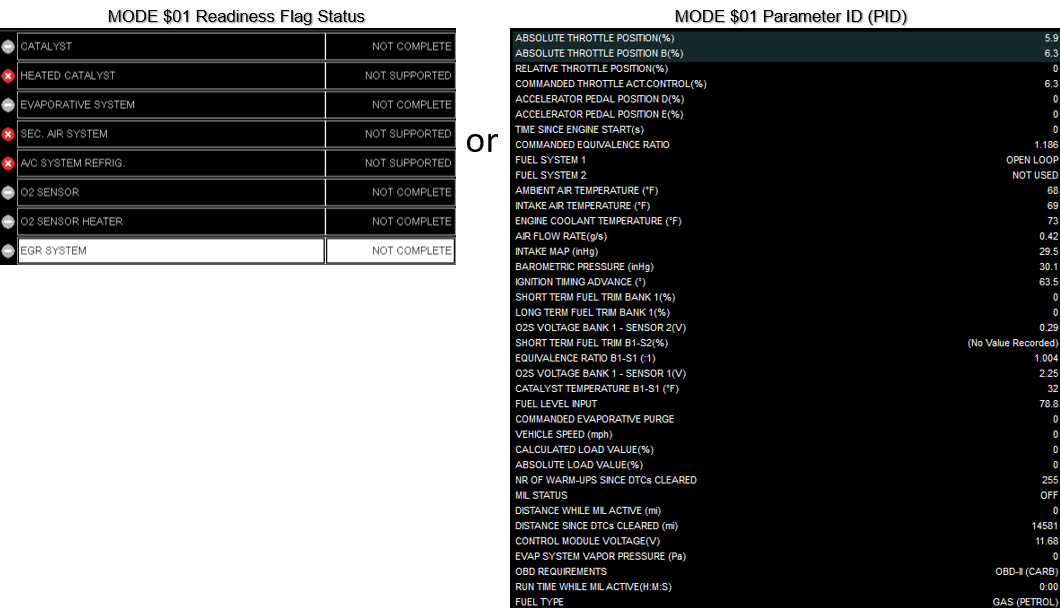
This capture shows the Toyota TECHSTREAM scan tool in the global mode. Toyota allows the readiness flag status and individual PIDs to be combined on one screen.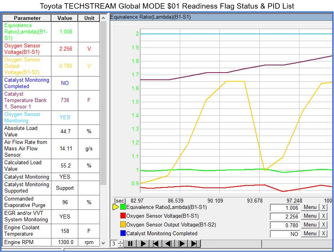
The scan tool engineers could solve this problem, and the request for information for MODE $01 could be combined, making it easier for the technician to look at the specific PIDs while driving and to watch the readiness flag status all on one page. I suspect they do this because state emission inspection programs need to request the readiness flag status, without the PIDs, as part of the pass/fail criteria.
DRIVE CYCLE VARIABLES
The purpose of this section is to show ECM operations that are not generally displayed for most vehicles. Seeing how they work will help the technician to visualize what is taking place in the background that could affect the completion of the various non-continuous monitor tests. These vehicles and factory scan tools at that time were used because they provided detailed information to help demonstrate the variables for completing non-continuous monitor tests.
- Is there a Minimum and Maximum time to run a monitor test?
- What are Fast Filter and Normal Filtering?
- What is Exhaust Time vs. Exhaust Temperature?
- What happens if driving conditions change during testing?
- What are Samples/Flow Counts?
- How can the CAT be Complete before the O2 is Complete?
- What are blocking conditions?
- What other things to look for during testing?
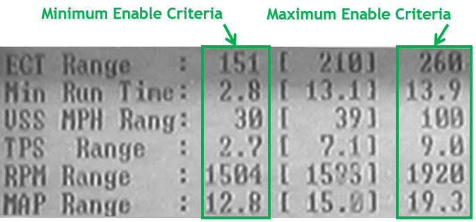
1. Is there a Minimum and Maximum time to run a Monitor Test(s)? This capture is from a Chrysler DRB III factory scan tool. It displays the Minimum and Maximum Enable Criteria (Time, Temp, Throttle, and Load) for the EGR monitor testing. While the maximum time for the monitor test is not easily located or even available, this proves that more extended periods of driving time are not practical. Take note of the Min Run Time of 2.8 minutes to a Max Run Time of 13.9 minutes. Multiple 15-20 minutes trips are better than a single trip of 20 miles or more.
2. What are Fast Filter and Normal Filtering? There are two ways to filter and monitor test results:
- Fast Filter: it is used for the first two drive cycles after a MODE $04 Diagnostics Clear is performed. This function clears DTCs and resets the readiness flag status to Not Complete. The trip must be ended after performing a memory reset, so make sure the turn the key off to end the trip. This procedure can make monitoring tests quicker during the next two trips. The ECM establishes a very tight pass value; if the vehicle meets this requirement, the monitor tests will complete. Think of it as a fast pass. This only occurs for the first two Drive Cycles after a MODE $04 Diagnostic Clear or low battery. Some Ford products don’t turn off after performing a MODE $04 Diagnostic clear; start driving. Monitor tests will run more quickly!
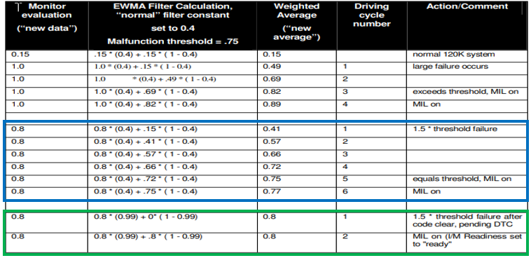
- Normal Filter: it is used for all subsequent after the two fast filter trips. The CAT, EGR, AFS/Secondary O2, and some EVAP monitor tests will require up to 6 trips to Pass/Fail the monitor tests. This can be why a readiness flag sometimes takes longer to complete. This capture shows an Exponentially Weighted Moving Average (EWMA) statistical process. EWMA is a process to ensure there are no false passes. It is not something you use to fix the vehicle, but having a basic knowledge of it will help to understand why a monitor test is not completing quickly even though everything has been done correctly!
An analogy would be the technician taking an ASE certification test. One attempt and done. What if ASE allowed a technician six shots and discarded the lowest and highest scores? A pass-or-fail ASE generates results after the other four test scores are averaged. The increased testing is a quality control protection against just getting by!
3. What is Throttle Open Time vs. Exhaust Open Time? This video, without audio, was captured from a Dodge using the factory tool. It demonstrates how the ECM Infers the temperature of the exhaust and CAT. It is part of the enable criteria to run monitor tests related to CAT and O2 readiness flags. Please think of this as superheating the CAT to prepare it for testing. After the throttle is held open, the assumption is made that the CAT is hot and ready for testing. Well, the PCM does the same thing more systematically.
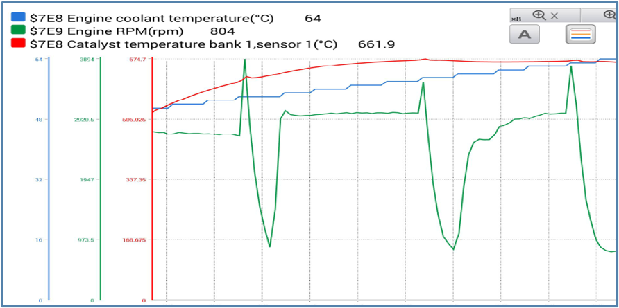
When using a Global Scan Tool (GST) on a CAN "C" equipped vehicle, this information will be displayed by the Catalyst Temperature PID under Current or Live Data. This is referred to as an Inferred Temperature. It is calculated by the ECM using Throttle Open Time, Intake Air Temperature, and Engine Load or Air Flow. A typical operational range for the CAT monitor test to run is 800°F to 1200°F.
4. What happens if driving conditions change during testing? This video, with audio, was captured from a Dodge using the factory tool to show the CAT monitor test running. Watch the Enable Conditions in the middle of the screen as they change with acceleration and deceleration. This indicates that a monitor test does not require perfect driving, driving conditions can change rapidly, and a monitor test can be suspended temporarily. Once the driver settles into a steady throttle and the Enable Conditions are again met, the monitor test will complete and report a "Done this Trip."
5. What are Samples/Flow Counts? This video, without audio, was captured by a GM using the factory tool. It shows the EGR monitor tests running during multiple decelerations while watching the video focuses on the EGR Flow Count as it increases. To increase the EGR Flow Counter during deceleration, the ECM monitors the MAP Voltage and Rpm change. Take note of the MAP voltage decreasing (High Vacuum, Low Pressure) during deceleration and then increasing (Lower Vacuum, Higher Pressure) as the EGR is opened slightly. This change increases intake manifold pressure and causes the engine Rpm to decrease if exhaust gases are being recirculated. It takes multiple samples averaged out to determine if EGR Flow is within acceptable limits. If testing is interrupted before completing the required monitor tests and conditions are again met during the same trip, the ECM will resume testing. If the trip is ended before testing is complete, the EGR Flow Count will reset to "0" at the next key-on event. Once again, this shows that a monitor test can run despite the driving conditions changing.

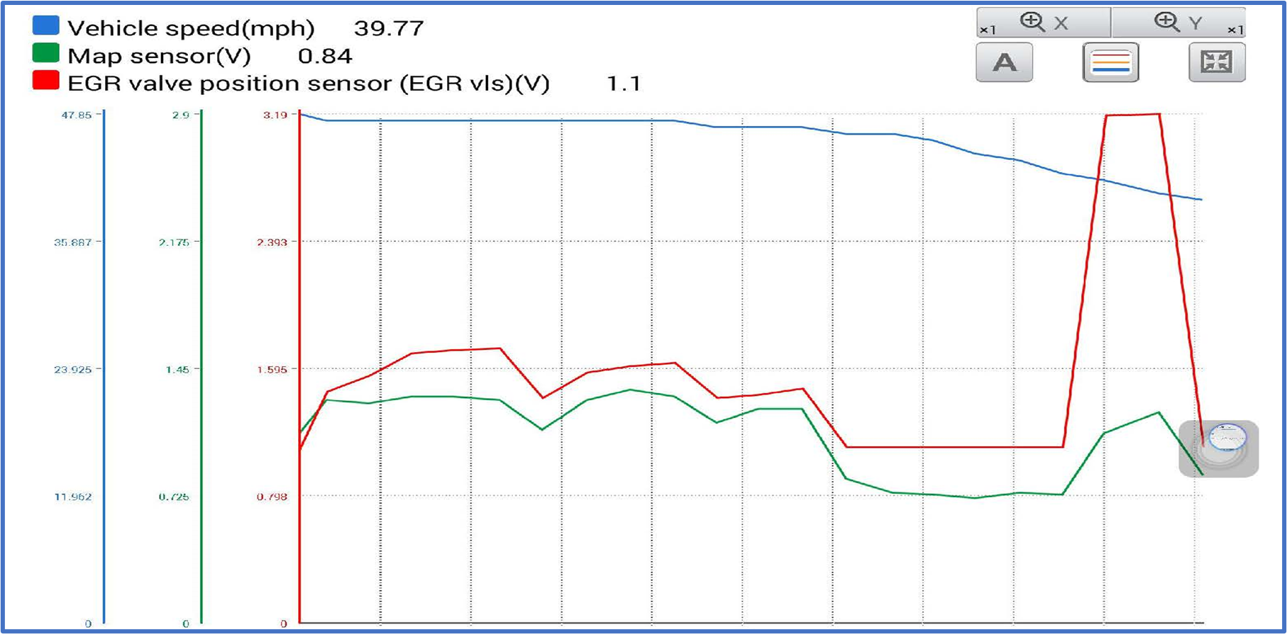
This graph was captured from a Honda Accord. The vehicle does not display a sample count in the data list, but the graph clearly shows the EGR being tested during deceleration. Look at the relationship between MAP and EGR Position Sensor; this reflects changes in intake manifold pressure during deceleration. The scaling makes it appear that EGR Valve Position Sensor is wide open. It is only partially available, as indicated by the 3.19v peak for a few milliseconds. When graphing scan data, always pay close attention to the ranging/scaling shown on the left; don't just look at the line changing.
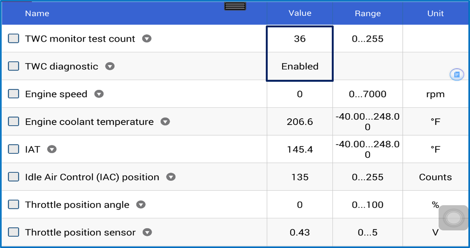
This video captured from a GM shows the CAT monitor test running; this can be seen by watching the TWC Monitor Test Count. When the monitor test runs, the TWC Monitor Test Count will increase. The TWC Diagnostic "Enabled" PID indicates that nothing prevents this test from running if the enable criteria are met. While the vehicle is being driven at cruise speed, the MAF g/s must be above 15 g/s and the Engine Run Time above the minimum specified time. Remember the video Pretest to Warm-up the Exhaust? This is the same thing. The TWC Monitor Test Count represents Samples collected by looking at the Switching Ratio of the HO2S1 B1 and HO2S B2. Watch it increase to 49 and roll over to 0 as the monitor test indicate testing is Complete.

There will be times when it is thought that a readiness flag Is not completed, so the vehicle is shut off. The car is restarted and then driven, and in a short time, the monitor testing is done, and the readiness flag is flipped to Complete. How could this happen? Testing began during the previous trip but ended before the ECM finished testing. In this case, the ECM retained the TWC Monitor Test Count of the prior cycle and started the next trip from that point. This enabled the monitor test to complete quickly during the next trip! Once again, this information will not be available from other vehicles. Remember that this is a background process that can affect the running and completion of a monitor test.
6. How can the CAT be Complete before the O2 is Complete? This video was captured from a LEXUS using the factory tool. The video demonstrates the O2 Sensor as a Parallel Monitor, which means the CAT monitor test is complete before the O2s. How can this happen? The ECM conducted enough monitor tests of the O2 to allow for testing of the CAT when enabling conditions were met before it finished monitor testing of the O2 sensors. Initially, the O2 data page shows the O2s as Complete, but the readiness flag page shows the O2 as incomplete. Please think of this as a fast pass; the ECM is running O2 some monitor tests, and they pass; now, the enabling conditions are suitable for performing the CAT test, so the ECM proceeds to run the CAT monitor test. Once the CAT monitor test is complete and the conditions are right again, the ECM will finish testing the O2 sensors. O2/AFRS monitor tests work together with the CAT monitor tests in parallel. In almost all situations where the CAT completes before the O2/AFRS, it is a given that the O2/AFRS monitor test will eventually pass. There are a few exceptions, as shown in MODE $09 In-Use Performance Monitor Tracking (INPMT) section.
No set order exists for individual readiness flag completion:
- If the CAT monitor test passes before the O2/AFS monitor tests have been completed, the ECM does not need to wait for the O2 to complete its monitor tests.
- If the Catalyst fails, the ECM may withhold completing the readiness flag until the O2 readiness flag is Complete.
This will change the speed at which the readiness flags are complete.
7. What is the blocking condition? Suppose a component, such as the oxygen sensor needed to evaluate the CAT efficiency or the EGR flow. In that case, the ECM may run the test and not record the CAT test result until the Oxygen Sensor test runs successfully. If the O2 sensor is marginal, the ECM will use EWMA to determine a pass or fail status.
In this example, the readiness flag status for the CAT will not be complete. WHY?
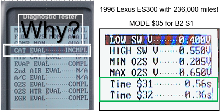 The typical response to this condition is to ask, why won’t the CAT readiness flag Complete? What am I doing wrong? When in doubt, ask what is the reporting component to the ECM? For the Catalyst, the reporting components are the front O2/AFS and rear O2 Sensors. In the capture on the right, how good are the test results? Are they marginal? If they pass, recheck the enable criteria for the monitor test in question, in this case, the CAT. In this case, MODE $06 test results were unavailable, so the next best place to look at was MODE $05 Oxygen Sensor Test Results because this was a pre-CAN vehicle. The highlighted box shows O2 Switch times that appear higher than usual. The PCM is holding judgment on the CAT readiness status until the Oxygen Sensors have enough time (EWMA) to determine if they are acceptable to pass judgment on the CAT(s).
The Bank 2 Sensor 1 O2 sensor was replaced, and below are the monitor test results.
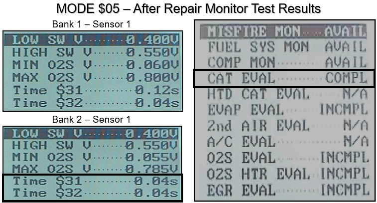
After installing a new Bank 2 (B2) Sensor 1 (S1) O2 sensor, take note of what readiness flag was completed first. Remember the previous screen? After replacing the B2 S1 O2 sensor, the CAT readiness flag was completed first. Eventually, the O2 readiness flag flipped to Complete. Now the question is, should both sensors be replaced because B1 S1 is showing some deterioration? That should be a discussion between the technician and the customer.
8. What other things to look for during testing?
- Is the vehicle reaching operating temperature?
- What quality AFS/O2 Sensors are installed?
- Have the tire sizes been radically changed?
- If the vehicle is a truck, does it appear to have any extra load?
- Can the Fuel Gauge for a pre-CAN "C" vehicle be believed? Is it reporting accurately?
- Diesel Truck with aftermarket “tuner” program installed?
- Has the vehicle been tuned? Are there any unsupported readiness flags that should be supported?
- Have any non-factory electrical load devices been installed?