Computer Controls Introduction
Introduction to Automotive Computer Controls
For years, automotive engineers found it challenging to design mechanical, vacuum, and hydraulic systems that consistently and accurately deliver the needed results. Systems strayed widely from the ideal air/fuel ratios because they could not monitor combustion or accurately control fuel delivery. They required elaborate emissions control systems to meet stringent exhaust emissions standards. These systems required much maintenance and sometimes were complicated, making them difficult to repair. If automotive engineers concentrated on increasing fuel economy and lowering emissions, performance and driveability would suffer. If they focused on reducing emissions, the economy, driveability, and performance would suffer. Electronic engine controls allow automotive engineers to restore good driveability, increase economy, lower exhaust emissions, and increase performance.
Good driveability is what the driver expects from a properly functioning engine, including easy starting, smooth idle, good acceleration through all speeds, instant response, and full power. Driveability concerns arise when a vehicle stalls, hesitates or stumbles, idles rough, surges, lacks power, is hard to start, or fails to start.
The official start of On-Board Diagnostics I (OBD I) was in 1988 (1). At that time, the California Air Resources Board (CARB) required that all vehicles sold new in California be equipped with a Check Engine Light (CEL). CARB required manufacturers to monitor the items in the area (2) below.
On-Board Diagnostics II (OBD II) was officially required to be equipped on all 1996 and newer passenger cars and light-duty trucks. Some manufacturers installed OBD II on 1994 and 1995 model-year vehicles. CARB required manufacturers to monitor the below.
The basic principles of Computer Fundamentals do not change. The foundation is always Input, Process, and Output. An important note is to look at where the scan tool is placed in the system. It takes processed data from the ECM/PCM and decodes it so the technician can read it. Remember that connecting a scan tool means adding another module to the network.

Computer Fundamentals
All computers rely on the principles of power and ground: generally, there are at least two battery feeds and two grounds. Computer operation is most reliable when the system voltage is 12-15 volts. The computer may enter a fail-safe mode if the operating voltage drops below ten or exceeds 17 volts.

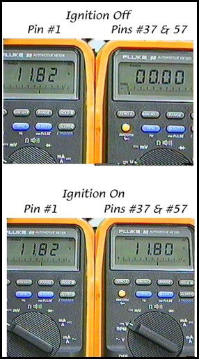
The ECM/PCM will have a Keep Alive Memory (KAM) that should always be B+. With the ignition in the Start or Run position, at least one, possibly two terminals, should have battery/charging voltage for proper ECM/PCM operation. The following pictures demonstrate these voltages. Note that the 11.82-volt key-on engine-off is lower than normal, so don't overlook a potential battery problem.
The quality of the connections at the battery and any ground point should always be considered. The ECM/PCM grounds can be located in various locations. They can be affected by corrosion, loose connections, and broken wire strands, which can lead to an increased voltage drop at these points.

Before 1990, a typical ground-to-ground voltage drop could be as high as .100v or 100mV. Since then, a typical ground-to-ground voltage drop is .050v or 50mV. If a higher-than-normal voltage drops at a ground connection, the ECM/PCM will see a higher-than-normal voltage reading from the affected circuit.

MORE CONTENT TO BE ADDED; PLEASE CHECK BACK!